About Tessellation
What tessellation is and how it works in Asset Transformer Studio
Read time 4 minutesLast updated 10 hours ago
To be displayed in a 3D application, CAD models' faces need to be translated into tessellated surfaces, also called meshes.
A mesh is composed of multiple connected polygons, or triangles (1 polygon generally equals 2 coplanar triangles), forming a discretized geometry that is understandable by a GPU, to be rendered in a 3D application.
The more triangles used to represent a surface, the more realistic the rendering, but the more computation is required.
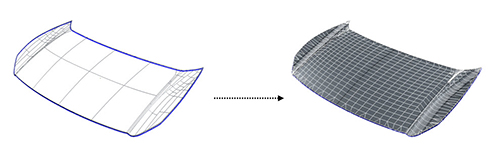
The tessellation step is very important in data preparation as it defines the maximum quality of the CAD model. The tessellation algorithm has proven to be very efficient at transforming any CAD model into meshes, ready to be displayed and exported, with a perfect balance between visual quality and polygon count.
The Tessellate function is available from the CAD menu.
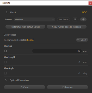
Parameters
Several parameters are used to control the tessellation, the most important ones being:
Parameter | Description |
|---|---|
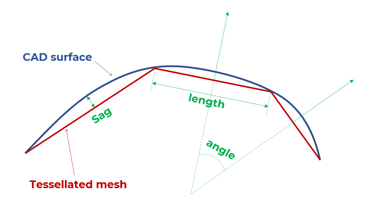
| Max Sag | The maximum distance between the geometry and the tessellation (also called "Chord error"). This parameter ensures that the mesh is similar enough to the original analytical CAD surface (exact geometry). A low value means that a very fine mesh is created. The distance values are expressed in millimeters. |
| Max Angle | The maximum angle allowed between normals of two adjacent polygons (on the same face). This provides more precision on small radius fillets. Adjust the |
| Max Length | Used to control the maximum length of a polygon (edge). For rendering, it is often recommended not to use the |
Example
In the example below, reducing the value from 0.2mm to 0.1mm made the mesh less rough and more realistic:
Max Sag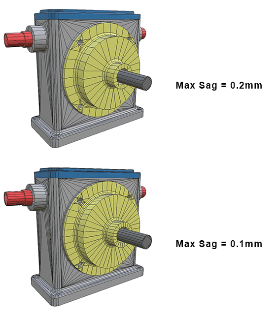
Then, adding the parameter (with a 20° value) has improved fillet precision by adding a row of polygons without increasing the polygon count for the yellow piece contour:
Max angle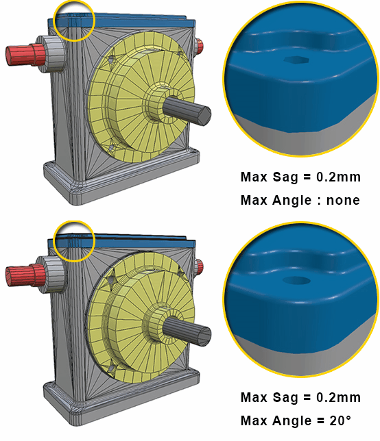
Presets
The Tessellate function comes with 4 default presets:
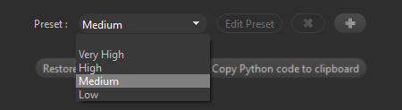
Preset | Description |
|---|---|
| Low | Delivers less accurate meshes. Use this preset for objects that will be seen from a distance, or for large objects with no details that need to be seen. |
| Medium (default) | Delivers well-balanced meshes. It is the default preset that will give the best result in most situations, a good average between polycount and visual quality. |
| High | Delivers more detailed meshes. Use this preset for objects that will be observed more closely (close to the virtual camera), or for objects that have small and important details. |
| Very High | Delivers super-detailed meshes. Use for objects that have small details that are important, or for very small objects, like rings, microchips… |
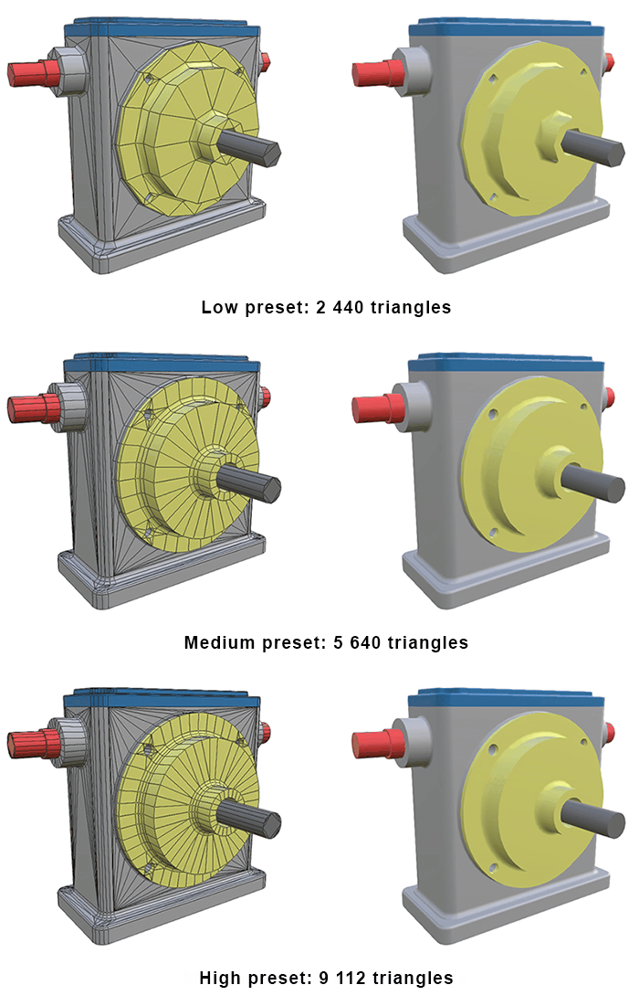
The difference of quality is very hard to distinguish, especially between and presets. With preset, the lack of polygons is starting to show.
MediumHighLowThis demonstrates that using the preset is most of the time the best solution, especially if you do not need to zoom closely on the model's details.
MediumTessellation and Part size
The is a distance criterion: a smaller value is necessary to guarantee a sufficient quantity of polygons on small parts.
Max SagA bigger Part in terms of scale does not mean that this part does not contain some potentially important details.
So, a small Sag value can also be used to maintain quality on detailed areas of bigger parts.
In the below example, the red beam (way bigger than the yellow ring) was tessellated with a 5 mm Sag, and 0.1 mm for the ring.
The result is that the hole in the beam was turned into a square: details on a big part were lost.
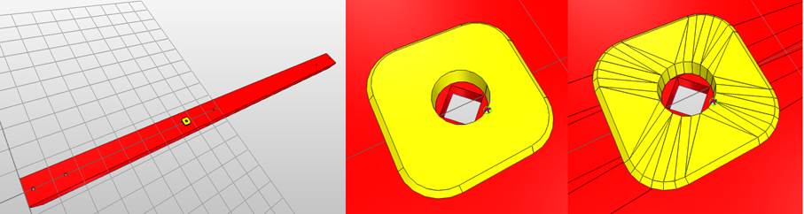
In a general approach, the best strategy is to find criteria (size, material, any metadata…) to perform a targeted tessellation, with different settings, based on these criteria.
About Re-tessellate
Models that contain BRep surfaces (CAD models) can be retessellated directly in the scene without having to import the model all over again. Re-Tessellate allows you to fine-tune tessellation quality of entire models or individual parts in the scene.