Rendering
EddyDenoiser
The denoiser node provides simple denoising of rendered images.
Usage
This node is used to denoise a rendered image.
Warning
If the denoiser node is being used to denoise the output of an EddyRender node directly, instead of denoising a saved image, then the progressive render option in the EddyRender node should be disabled. Attempting to denoise a progressive render will perform poorly as every intermediate progressive result will be passed to the denoiser node by Nuke.
Note
If the input image is high dynamic range then this should be specified to ensure the denoiser engine handles it correctly.
Inputs/Outputs
Connections |
ClassType |
Number |
Description |
|---|---|---|---|
image |
image |
1 |
Source image to be denoised. |
Output |
image |
1 |
The denoised result image. |
Controls
Parameter |
Values |
Description |
|---|---|---|
HDR |
True/False |
Specifies if the input image is a high dynamic range image. |
EddyEnvironmentLight
This node creates a light source from an environment map.
Usage
Use as input light source to the Eddy render node.
Inputs/Outputs
Connections |
ClassType |
Number |
Description |
|---|---|---|---|
map |
map |
0-1 |
A Nuke environment map |
axis |
axis |
0-1 |
A Nuke axis node representing a transformation applied to the channel |
Output |
EddyLight |
1 |
An Eddy light for use with the Eddy rendering node |
Controls
Parameter |
Values |
Description |
|---|---|---|
Color |
Color |
Color of the light source, scales the intensity |
Intensity |
0…inf |
Intensity of the light |
Visibility flags (multiple) |
True/False |
Controls the visibility of the environment light to the various types of rays. For example, disabling the camera visibility will prevent the environment map from appearing as a background in the rendered image. Disabling specular reflection will remove the environment map from any specular or glossy reflections. |
Object tags |
Text |
Tags which can be used to identify this light in light path expressions for AOVs. Multiple tags can be specified, separated by spaces or commas. |
EddyLight
This node is used to create point lights and quadrilateral area lights. For other light types the native Nuke nodes are used.
Usage
Use as input light source to the Eddy render node.
Inputs/Outputs
Connections |
ClassType |
Number |
Description |
|---|---|---|---|
axis |
axis |
0-1 |
A Nuke axis node representing a transformation applied to the channel |
Output |
EddyLight |
1 |
An Eddy light for use with the Eddy rendering node |
Controls
Parameter |
Values |
Description |
|---|---|---|
Type |
List |
Specifies the light type, either point or quadrilateral area. |
Color |
Color |
Color of the light source, scales the intensity. |
Intensity |
0…inf |
Intensity of the light. Units are W for point lights, or W/m^2 for area lights. |
Falloff |
List |
Controls to what degree the light intensity goes down with distance from the light source. Can be none, linear, quadratic, or cubic. |
Controls for quadrilateral area lights
Parameter |
Values |
Description |
|---|---|---|
Camera visible |
True/False |
For quadrilateral area lights, controls whether the light itself appears in the rendered image. |
Inner falloff |
0…90 |
Specifies an inner falloff cone angle which can be used to give this light a directional behavior. The default of 90 degrees creates a standard diffuse emitter. |
Outer falloff |
0…90 |
Specifies an outer falloff cone angle which can be used to give this light a directional behavior. The default of 90 degrees creates a standard diffuse emitter. |
Two-sided |
True/False |
Controls whether the light should emit from just one side or both sides of the quadrilateral. For one sided lights the viewport displays which side is the emitter. |
EddyMeshLight
This node is used to create a light from a mesh.
Usage
Use as input light source to the Eddy render node.
Inputs/Outputs
Connections |
ClassType |
Number |
Description |
|---|---|---|---|
mesh |
mesh |
1 |
A mesh geometry to use as the light source. |
Output |
EddyLight |
1 |
An Eddy light for use with the Eddy rendering node |
Controls
Parameter |
Values |
Description |
|---|---|---|
Intensity |
0…inf |
Intensity of the light. Units are W/m^2. |
Falloff mode |
List |
Controls to what degree the light intensity goes down with distance from the light source. Can be none, linear, quadratic, or cubic. |
Inner falloff |
0…90 |
Specifies an inner falloff cone angle which can be used to give this light a directional behavior. The default of 90 degrees creates a standard diffuse emitter. |
Outer falloff |
0…90 |
Specifies an outer falloff cone angle which can be used to give this light a directional behavior. The default of 90 degrees creates a standard diffuse emitter. |
Two-sided |
True/False |
Controls whether the light should emit from just one side or both sides of the mesh. Use with care, setting this when it is not needed (e.g. on a closed mesh) will reduce the lighting quality. |
Visibility flags (multiple) |
True/False |
Controls the visibility of the mesh light to the various types of rays. For example, disabling the camera visibility will prevent the light itself from appearing in the rendered image. |
Object tags |
Text |
Tags which can be used to identify this light in light path expressions for AOVs. Multiple tags can be specified, separated by spaces or commas. |
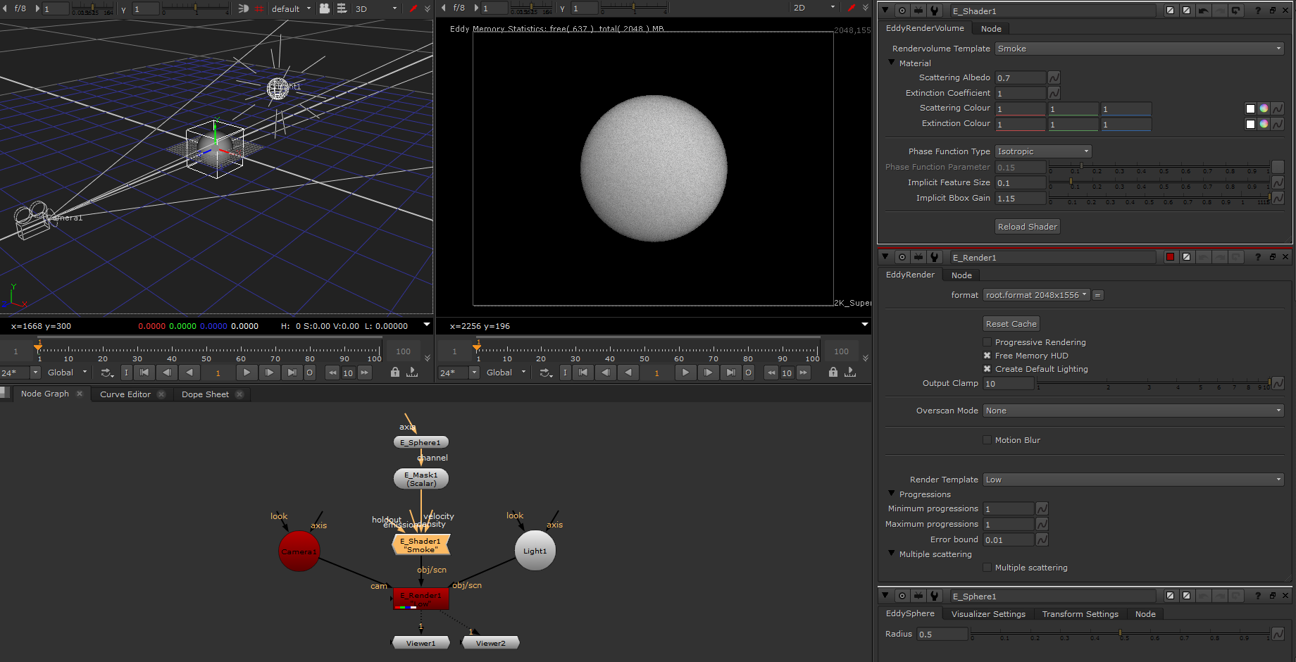
EddyRender
The render node is responsible for rendering the final image. It takes as input the volumetric primitives, surface meshes, the lights and holdouts, and outputs an image using the render settings provided.
The render node is capable of rendering both deep and regular images. If the downstream node requests deep data then deep data will be rendered, otherwise a regular image is rendered.
Note
For more information about rendering in Eddy see the Rendering section of the documentation.
Inputs/Outputs
Connections |
ClassType |
Number |
Description |
|---|---|---|---|
cam |
CameraOp |
1 |
A camera through which the frame will be rendered |
obj/scn |
EddyRenderable |
0+ |
Zero or more Eddy renderable node defining an object in the scene (can be a mesh, SDF, volume, or combination mesh and volume). |
EddyRenderableMesh |
0+ |
Zero or more Eddy renderable mesh node defining a mesh object in the scene. |
|
EddyRenderableVolume |
0+ |
Zero or more Eddy renderable volume node defining a volume object in the scene. |
|
EddyLight |
0+ |
Zero or more Eddy light nodes defining the lighting of the scene. |
|
LightOp |
0+ |
Zero or more Nuke light nodes defining the lighting of the scene. |
|
EddyMeshLight |
0+ |
Zero or more Eddy mesh light nodes defining the mesh lights in the scene. |
|
EddyEnvironmentLight |
0+ |
Zero or more Eddy environment light nodes defining the environment lighting for the scene. |
|
Outputs |
Iop/DeepOp |
1 |
The rendered frame represented as a Nuke Iop or DeepOp |
Main controls
Parameter |
ValueType |
Description |
|---|---|---|
Progressive Rendering |
True/False |
Enables progressive rendering in the viewport. |
Free Memory HUD |
True/False |
Shows a HUD in the viewport displaying the used and free GPU memory |
Create Default Lighting |
True/False |
Create some default lighting when no lights are plugged in to this node. This allows you to quickly render something before you set up your proper lighting. If you actually want no lighting then disable this. |
Overscan Mode |
List |
Specify overscan mode to increase the rendered region. |
Overscan (percent) |
0…inf |
Specify overscan amount in the form of a percentage. Eg. 5.0 would mean 5% overscan. |
Overscan (pixels) |
0…inf |
Specify overscan amount in pixels. Eg. 25 would expand the top/bottom/left/right edges of the render by 25 pixels. |
Maximum samples |
1…inf |
The maximum number of samples (camera samples, AA samples) to use for each pixel. This is the main quality control, increasing this will reduce noise. |
Adaptive error bound |
0…inf |
The allowed error in the color value of each pixel. Once the pixel color has been determined to within this accuracy, no further samples will be taken by this pixel. Set to zero to disable adaptive sampling. |
Absolute error |
True/False |
Requests that the adaptive error bound is an absolute error rather than a relative error. A relative error is a percentage error in the value of the pixel, whereas an absolute error is the same whether or not the pixel is bright or dark. |
Maximum ray depth |
1…inf |
The maximum allowed ray depth, e.g. a value of 1 means direct lighting only, 2 means at most one indirect bounce. Can be set to -1 for unlimited ray depth. |
Motion Blur |
True/False |
Enables rendering of motion blur |
Shutter Mode |
List |
The shutter mode for motion blur calculations |
Shutter Angle |
0…360 |
The shutter angle controls the amount of motion blur, measured in degrees |
Pixel filter type |
List |
The type of pixel filter to use. |
Pixel filter size |
1…inf |
Size of the pixel filter. |
Deep Sample Scale |
0…inf |
Scale for the size the deep sample depths, measured as a multiple of the voxel size |
Max Deep Samples Per Pixel |
1…inf |
Maximum number of deep samples per pixel |
Volume setting controls
The default behavior of the render node is to automatically choose the volume rendering settings. These are based on the properties of the volume which is being rendered, and also on the maximum number of samples that are requested.
Sometimes it will be necessary to select manual settings, for example if the settings chosen automatically were less than ideal. When using manual settings care must be taken to ensure they are valid. If they are not valid (e.g. using the wrong emission type or raymarching an implicit volume with the wrong step size) then the resulting image will be incorrect also.
Also note that each individual renderable volume can choose to override these global settings with their own unique settings.
Parameter |
ValueType |
Description |
|---|---|---|
Settings mode |
List |
Selects between automatically choosing the volume settings or specifying them manually. |
Integrator type |
List |
The type of volume integrator to use, either raymarching or tracking. If ‘Mixed’ is chosen then the integrator type can be specified for each ray type separately. |
Primary integrator type |
List |
The type of integrator to use for primary rays. |
Primary transmittance integrator type |
List |
The type of integrator to use for primary transmittance rays. |
Secondary integrator type |
List |
The type of integrator to use for secondary rays. |
Secondary transmittance integrator type |
List |
The type of integrator to use for secondary transmittance rays. |
Emission type |
List |
The type of emission found in this volume. |
Supervoxels |
True/False |
Enables hierarchical supervoxels to potentially speed up rendering |
Equi-angular sampling |
True/False |
Enables equi-angular sampling in the integrators. See Equi-angular sampling. |
Thin media sampling |
True/False |
Enables thin media sampling for the tracking integrator. See ThinMediaLabel. |
Sample count multiplier |
0…inf |
A multiplier for the number of volume samples taken by each ray. Use to boost the sample count for a particular volume without affecting the others. Use the global volume samples setting instead of this to affect all the volumes in a scene. |
Raymarch step size override |
0…inf |
Overrides the step size to use for raymarching integrators. Leave this as zero to use the default voxel size. This is required to be set to raymarch implicit volumes that are not voxelized as they do not have a voxel size. |
Raymarch step scale |
0…inf |
Scale which increases the step size used by the raymarching integrators. Increasing the step size will be faster, but results will not be accurate. |
Raymarch transmittance step scale |
0…inf |
Scale which increases the step size used by the raymarching transmittance integrators. Increasing the step size will be faster, but results will not be accurate. |
Advanced controls
Parameter |
ValueType |
Description |
|---|---|---|
Direct light samples |
1…inf |
The number of direct light samples to take at each surface shading point. |
Volume samples |
1…inf |
The number of lighting samples that should be taken inside a volume for each camera sample ray. |
Volume indirect samples |
1…inf |
The number of indirect lighting samples that should be taken inside a volume for each camera sample ray. |
Indirect samples |
1…inf |
The number of indirect surface lighting samples that should be taken for each camera sample ray. This affects all types of indirect samples, so it is not required to also increase the specific types below. |
Indirect diffuse samples |
1…inf |
The number of indirect diffuse reflection samples that should be taken for each camera sample ray. |
Indirect reflection samples |
1…inf |
The number of indirect reflection samples that should be taken for each camera sample ray. Includes both specular and glossy reflections. |
Indirect refraction samples |
1…inf |
The number of indirect refraction samples that should be taken for each camera sample ray. Includes both specular and glossy transmission through the surface. |
Indirect subsurface samples |
1…inf |
The number of indirect subsurface samples (i.e. diffuse transmission samples) that should be taken for each camera sample ray. |
Enable direct lighting MIS |
True/False |
Enables multiple importance sampling (MIS) for direct light sampling. This should usually be enabled unless it is found to be causing a problem. |
Direct light clamp |
0…inf |
Clamped maximum value for the direct lighting contribution from each camera sample. |
Indirect light clamp |
0…inf |
Clamped maximum value for the indirect lighting contribution from each camera sample. |
Velocity maximum value |
0…inf |
If non-zero the velocity outputs will be clamped to this and re-scaled so that 0.0 corresponds to -max, 1.0 corresponds to +max. |
Velocity per-frame units |
True/False |
Specifies if velocity outputs should be per-frame, or per-second. |
Motion type |
List |
Controls the motion type for the ‘motion’ output channel only. Note that we also have the ‘motion_forward’ and ‘motion_backward’ channels, so it is possible to generate all motion types in a single render pass. |
Motion maximum value |
0…inf |
If non-zero the motion outputs will be clamped to this and re-scaled so that 0.0 corresponds to -max, 1.0 corresponds to +max. |
Motion per-frame units |
True/False |
Specifies if motion outputs should be per-frame, or per-second. |
Camera projection |
List |
The type of camera projection to use for the render |
Rendering a sphere as a smoke volume using a smoke shader |
EddyRenderable
The renderable node is the general purpose node for placing renderable objects in the scene. It supports shader networks, SDFs, meshes, volumes, and combinations such as volumes enclosed inside a mesh. Works together with the ShaderRefLabel node to define the surface and/or volume materials.
For simple meshes and volumes, use the RenderableMeshRefLabel or RenderableVolumeRefLabel nodes instead.
Usage
The Eddy renderable node is used as input to the Eddy render node.
Inputs/Outputs
Connections |
ClassType |
Number |
Description |
|---|---|---|---|
mesh |
mesh |
0-1 |
An optional mesh geometry to provide the rendered surface geometry. |
sdf |
EddyChannel |
0-1 |
An optional Eddy SDF channel to define the rendered surface geometry. |
shaders |
EddyShader |
1-2 |
The shaders to define the surface and volume materials. Either a surface or a volume shader may be provided, or both can be used to define a volume inside a translucent surface. See the ShaderRefLabel node. |
Output |
EddyRenderable |
1 |
An Eddy renderable for use with the Eddy rendering node |
Controls
Parameter |
Values |
Description |
|---|---|---|
SDF minimum feature size |
0-inf |
Optionally specifies the feature size for implicit SDF surfaces, to control the step size when calculating ray intersections with the SDF. Only required for implicit surfaces. |
SDF sharpness |
0-inf |
Controls the sharpness of hard corners in the SDF. |
Volume setting controls
By default the global volume settings from the EddyRender node will be used for this renderable. If customized settings for this renderable are required they can be enabled here. The volume settings for this renderable can be either determined automatically, or specified manually.
Parameter |
ValueType |
Description |
|---|---|---|
Settings mode |
List |
Selects between using the global volume settings, or customized settings for this renderable only. Customized settings can be automatic or specified manualally. |
Integrator type |
List |
The type of volume integrator to use, either raymarching or tracking. If ‘Mixed’ is chosen then the integrator type can be specified for each ray type separately. |
Primary integrator type |
List |
The type of integrator to use for primary rays. |
Primary transmittance integrator type |
List |
The type of integrator to use for primary transmittance rays. |
Secondary integrator type |
List |
The type of integrator to use for secondary rays. |
Secondary transmittance integrator type |
List |
The type of integrator to use for secondary transmittance rays. |
Emission type |
List |
The type of emission found in this volume. |
Supervoxels |
True/False |
Enables hierarchical supervoxels to potentially speed up rendering |
Equi-angular sampling |
True/False |
Enables equi-angular sampling in the integrators. See Equi-angular sampling. |
Thin media sampling |
True/False |
Enables thin media sampling for the tracking integrator. See ThinMediaLabel. |
Sample count multiplier |
0…inf |
A multiplier for the number of volume samples taken by each ray. Use to boost the sample count for a particular volume without affecting the others. Use the global volume samples setting instead of this to affect all the volumes in a scene. |
Raymarch step size override |
0…inf |
Overrides the step size to use for raymarching integrators. Leave this as zero to use the default voxel size. This is required to be set to raymarch implicit volumes that are not voxelized as they do not have a voxel size. |
Raymarch step scale |
0…inf |
Scale which increases the step size used by the raymarching integrators. Increasing the step size will be faster, but results will not be accurate. |
Raymarch transmittance step scale |
0…inf |
Scale which increases the step size used by the raymarching transmittance integrators. Increasing the step size will be faster, but results will not be accurate. |
Visibility controls
Parameter |
Values |
Description |
|---|---|---|
Visibility flags (multiple) |
True/False |
Controls the visibility of the renderable to the various types of rays. For example, disabling the camera visibility will prevent the renderable from appearing in the main image while still allowing it to appear in reflections. Disabling shadow visibility will stop the renderable from casting shadows. |
Object tags |
Text |
Tags which can be used to identify this renderable in light path expressions for AOVs. Multiple tags can be specified, separated by spaces or commas. |
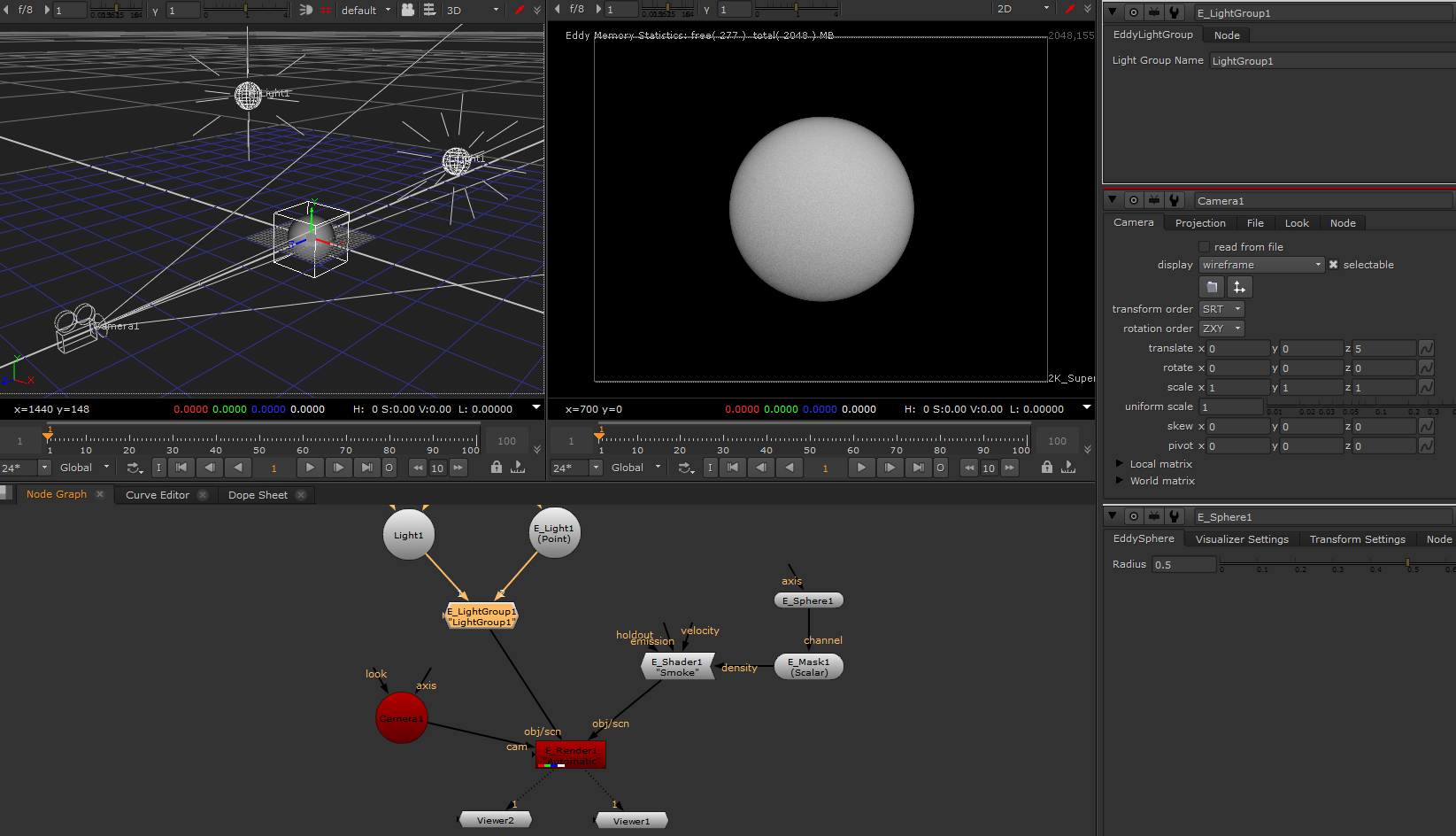
EddyRenderableGroup
The renderable group node allows for assigning the same tags to a collection of lights or renderables simultaneously. These tags can be used to identify the lights and renderables in light path expressions for AOVs.
Usage
The output of the renderable group node can be used as an input to the Eddy render node. The effect is as if the tags were specified on each light and renderable individually, so this node simply provides an easier way to set the tags on a collection of lights or renderables.
Inputs/Outputs
Connections |
ClassType |
Number |
Description |
|---|---|---|---|
1,2,3… |
LightOp / EddyLight / EddyRenderable |
1+ |
One or more Nuke lights, Eddy lights, or Eddy renderables. |
Controls
Parameter |
Values |
Description |
|---|---|---|
Object tags |
Text |
Tags which can be used to identify these objects in light path expressions for AOVs. Multiple tags can be specified, separated by spaces or commas. |
A light group named ‘LightGroup1’ created from Nuke and Eddy point lights |
EddyRenderableMesh
The renderable mesh node describes a mesh with a surface material that is placed in the scene. The inputs and attributes on the node will dynamically change based on the material that is selected.
Usage
The Eddy renderable mesh node is used as input to the Eddy render node.
Common Inputs/Outputs
Connections |
ClassType |
Number |
Description |
|---|---|---|---|
Outputs |
EddyRenderableMesh |
1 |
An Eddy renderable mesh for use with the RenderRefLabel node. |
Controls
Parameter |
Values |
Description |
|---|---|---|
Material |
List |
Selects the surface material to use. This will change the available inputs and attributes on the node. See Standard Surface Materials for more details. |
Visibility controls
Parameter |
Values |
Description |
|---|---|---|
Visibility flags (multiple) |
True/False |
Controls the visibility of the mesh to the various types of rays. For example, disabling the camera visibility will prevent the mesh from appearing in the main image while still allowing it to appear in reflections. Disabling shadow visibility will stop the mesh from casting shadows. |
Object tags |
Text |
Tags which can be used to identify this mesh in light path expressions for AOVs. Multiple tags can be specified, separated by spaces or commas. |
EddyRenderableVolume
The renderable volume node describes a volumetric primitive which can be placed in the scene. The inputs and attributes will dynamically change based on the material that is selected.
See Standard Volume Materials for descriptions of all the available volume materials and their parameters.
Usage
The Eddy renderable volume node is used as input to the Eddy render node.
Common Inputs/Outputs
Connections |
ClassType |
Number |
Description |
|---|---|---|---|
Inputs |
EddyChannel |
0+ |
Eddy channel(s) containing volume data for the material. The specific set of available input channels is determined by the selected material. |
Outputs |
EddyRenderableVolume |
1 |
An Eddy renderable volume for use with the RenderRefLabel node. |
Controls
Parameter |
Values |
Description |
|---|---|---|
Material |
List |
Selects the volume material to use. This will change the available inputs and attributes on the node. See Standard Volume Materials for more details. |
Volume setting controls
By default the global volume settings from the EddyRender node will be used for this volume. If customized settings for this volume are required they can be enabled here. The volume settings for this volume can be either determined automatically, or specified manually.
Parameter |
ValueType |
Description |
|---|---|---|
Settings mode |
List |
Selects between using the global volume settings, or customized settings for this volume only. Customized settings can be automatic or specified manualally. |
Integrator type |
List |
The type of volume integrator to use, either raymarching or tracking. If ‘Mixed’ is chosen then the integrator type can be specified for each ray type separately. |
Primary integrator type |
List |
The type of integrator to use for primary rays. |
Primary transmittance integrator type |
List |
The type of integrator to use for primary transmittance rays. |
Secondary integrator type |
List |
The type of integrator to use for secondary rays. |
Secondary transmittance integrator type |
List |
The type of integrator to use for secondary transmittance rays. |
Emission type |
List |
The type of emission found in this volume. |
Supervoxels |
True/False |
Enables hierarchical supervoxels to potentially speed up rendering |
Equi-angular sampling |
True/False |
Enables equi-angular sampling in the integrators. See Equi-angular sampling. |
Thin media sampling |
True/False |
Enables thin media sampling for the tracking integrator. See ThinMediaLabel. |
Sample count multiplier |
0…inf |
A multiplier for the number of volume samples taken by each ray. Use to boost the sample count for a particular volume without affecting the others. Use the global volume samples setting instead of this to affect all the volumes in a scene. |
Raymarch step size override |
0…inf |
Overrides the step size to use for raymarching integrators. Leave this as zero to use the default voxel size. This is required to be set to raymarch implicit volumes that are not voxelized as they do not have a voxel size. |
Raymarch step scale |
0…inf |
Scale which increases the step size used by the raymarching integrators. Increasing the step size will be faster, but results will not be accurate. |
Raymarch transmittance step scale |
0…inf |
Scale which increases the step size used by the raymarching transmittance integrators. Increasing the step size will be faster, but results will not be accurate. |
Visibility controls
Parameter |
Values |
Description |
|---|---|---|
Visibility flags (multiple) |
True/False |
Controls the visibility of the volume to the various types of rays. For example, disabling the camera visibility will prevent the volume from appearing in the main image while still allowing it to appear in reflections. Disabling shadow visibility will stop the volume from casting shadows. |
Object tags |
Text |
Tags which can be used to identify this volume in light path expressions for AOVs. Multiple tags can be specified, separated by spaces or commas. |
Rendering a sphere as a smoke volume using a smoke shader |
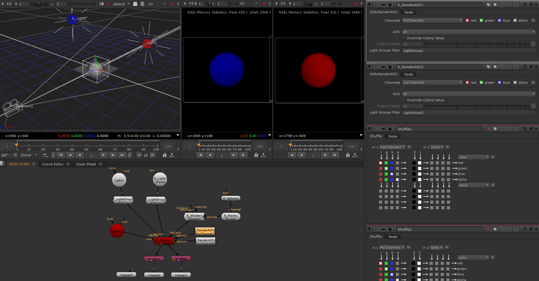
EddyRenderAOV
The Eddy render AOV node allows assigning output variables to Nuke channels. It can be used together with the RenderableGroupRefLabel to select different lights and objects for inclusion in the AOV.
AOV (Arbitrary Output Variable) nodes provide a mechanism to output different shader components into different channels. This allows individual control and processing (for example filtering) of each shader component of the final image.
The AOV node allows the type of AOV to be chosen from a large list of predefined AOVs, each of which can be modified with the light filter to include only the specified lights. Alternatively custom AOV types can be defined, using light path expressions and specifying the AOV mode and behavior.
Usage
The Eddy render AOV is used as input to the Eddy render node allowing the user to generate AOVs in the Eddy rendering process.
Inputs/Outputs
Connections |
ClassType |
Number |
Description |
|---|---|---|---|
Output |
EddyRenderAOV |
1 |
An Eddy render AOV for use with the Eddy render node |
Controls
Parameter |
Values |
Description |
|---|---|---|
Channels |
List |
The Nuke channel used to store this set of AOVs |
AOV |
List |
The predefined AOV that should be output to the selected channel. Alternatively can be set to ‘Custom / Light Path Expression’ to manually define the AOV. |
Light Tag Filter |
Text |
An optional tag which will match and include only lights with this tag in the AOV. The special name ‘default’ can be used to match lights without any tag assigned. |
Allow Deep |
True/False |
Controls whether this AOV will generate deep output, when deep data is requested from the RenderRefLabel node. Disabling deep data when it is not needed can save a significant amount of memory. Note that some built-in outputs will disable deep output regardless of this setting (e.g. statistics such as ‘samplEddycount’ or ‘ray_count’). |
Clamped |
True/False |
Controls whether clamping will be applied to samples for this AOV. The RenderRefLabel node specifies the clamping settings. Note that some built-in outputs will disable clamping regardless of this setting (e.g. statistics such as ‘samplEddycount’ or ‘ray_count’). |
Custom AOV controls
When the AOV type is set to ‘Custom / Light Path Expression’, additional controls become available to specify the light path expression and the settings for this output.
See Custom and Advanced AOVs and Light path expressions for more details about creating custom AOVs and light path expressions.
Parameter |
Values |
Description |
|---|---|---|
Name/LPE |
Text |
The predefined name of the output (such as ‘beauty’, or ‘indirect’), or a light path expression. |
Output Type |
List |
Controls what type of values are stored in this output. |
Output Mode |
List |
Controls how values are accumulated into this output. |
Output Holdout Mode |
List |
Controls whether holdouts will be included in this output. |
Clamp positive |
True/False |
Specifies if this output should be clamped to be positive. Note that some built-in outputs will disable positive clamping regardless of this setting (e.g. position or velocity outputs). |
Filter NaN values |
True/False |
Specifies if this output should remove NaN values. Usually recommended unless you are debugging a custom shader. |
Filter infinite values |
True/False |
Specifies if this output should remove infinite values. |
Warning
When entering a LPE into Nuke, any “[” characters must be escaped, i.e. replaced with “\[”. This is because Nuke interprets “[” as the start of a TCL script expression. The backslash tells Nuke to leave it alone and pass it through unchanged to Eddy.
If you get an error like “Failed to tokenize light path expression ‘RV: Unknown command’” then it is due to a missing “\\”. Without this Nuke replaces the light path expression with “Unknown command” which then causes an error in Eddy.
A red and a blue point light grouped into two light groups and rendered separately using the Eddy render AOV node. |
EddyShader
The Eddy shader node is used to define materials and shader networks that can be used with the RenderableRefLabel node.
See Standard Surface Materials and Standard Volume Materials for descriptions of the standard materials.
See Shader Networks for more information on how to use this node to create custom shader networks.
Usage
The Eddy shader node is used as input to the RenderableRefLabel node.
Inputs/Outputs
Connections |
ClassType |
Number |
Description |
|---|---|---|---|
Output |
EddyShader |
1 |
An Eddy shader for use with the RenderableRefLabel node. |
Controls
Parameter |
Values |
Description |
|---|---|---|
Shader |
List |
Selects the shader function to use. This will change the available inputs and attributes on the node. |
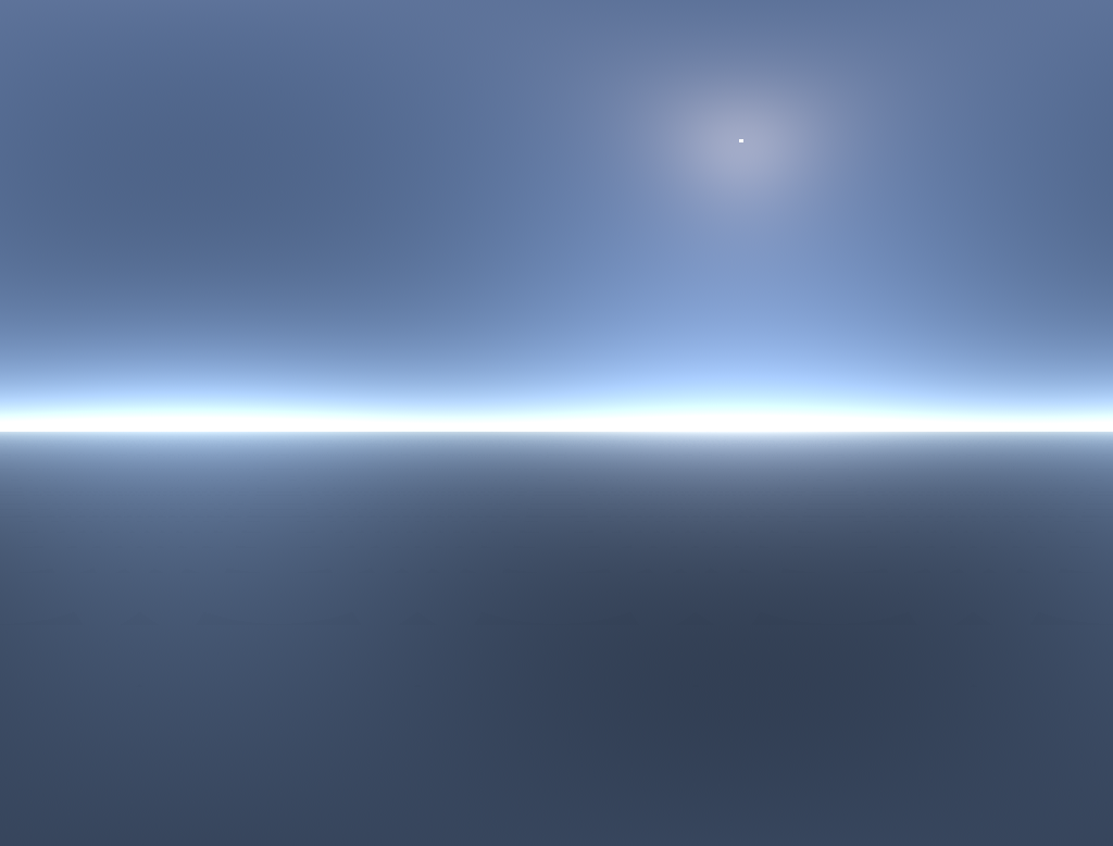
EddySunSky
Creates an image of the sky and optionally the sun, suitable for use as an environment light, based on various physical and standardized sky models. Can also be used to compute atmospheric hazing for an image.
Usage
The SunSky node provides multiple alternative sky models, both based on physically simulated atmospheric models and various standardized models. The image produced by the SunSky node can be used as the input to an environment light node.
The sky models supported are as follows:
Physical: This calculates the sky color by tracing rays through a model of the atmosphere. It therefore produces correct results even when the sun is very low, and can also calculate the sky as it appears at different heights above ground.
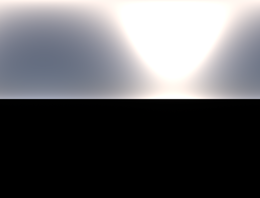
Physical spectral: This is similar to the physical model, but colors are calculated using a full spectral simulation instead of just using an RGB triple. The result is usually slightly better than the physical model, although it does take a bit longer to calculate.
Preetham-Shirley-Smits: This is an approximate model that attempts to match a physical model as closely as possible. It does not have as many parameters as a physical model, and although it is only approximate it is very fast to calculate.
CIE Standard: This provides the CIE standardized sky models. These are a variety of luminance only (i.e. monochrome) equations that model various sky conditions.
CIE Traditional Overcast: The CIE Traditional Overcast sky model approximates the luminance only (i.e. monochrome) of an overcast sky.

Physical spectral sky model animated over a 16 hour dawn to dusk period¶ |

Physical spectral sky model¶ |
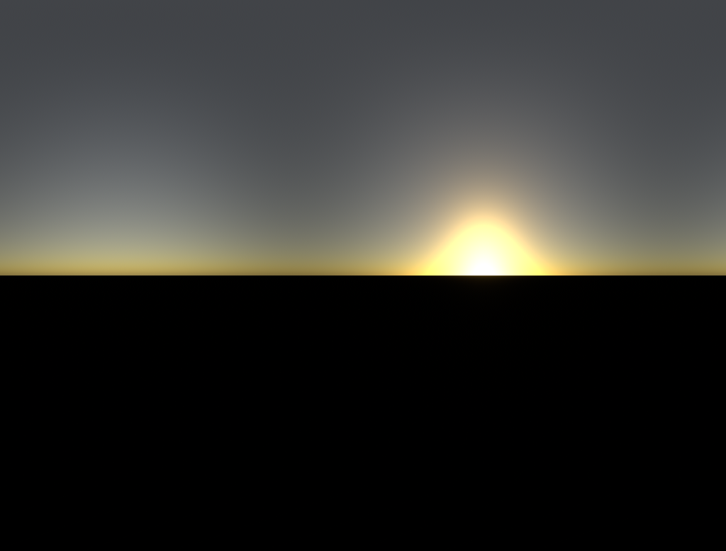
Physical spectral sky model at sunset¶ |
Physical spectral sky model at 3km above ground level¶ |
Physical spectral sky model with increased Mie scattering to simulate pollution¶ |

Preetham-Shirley-Smits sky model¶ |
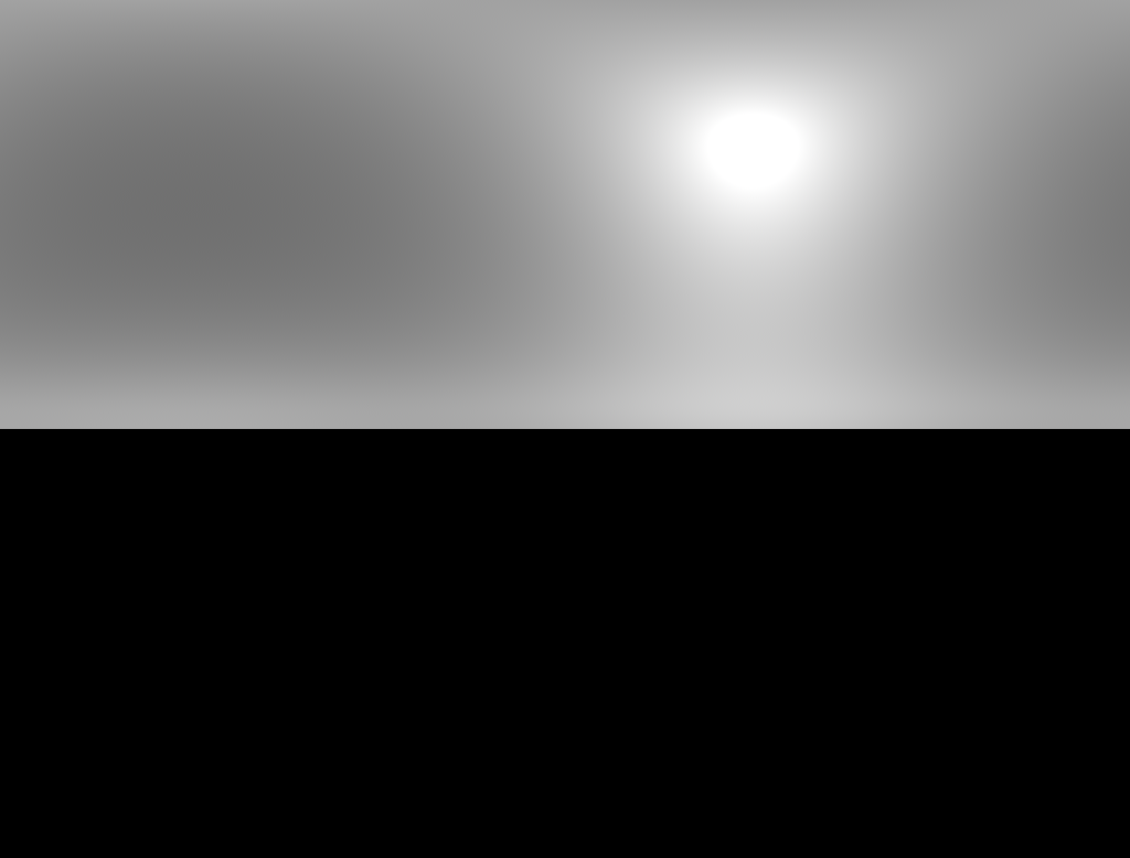
CIE Standard sky model number 12¶ |
Atmospheric hazing
The physical sky models can also be used to compute atmospheric hazing images for compositing over a source image. The deep source image and camera are passed as inputs to the EddySunSky node, which will then use the depth data to clip the atmospheric rays. The haze image can then be composited over the original source image.
Note
To correctly composite the haze image over the original image, the colored alpha channels (AR, AG, AB) should be used instead of the regular single alpha channel. The MergeExpression node can be used to do this, take a look at the example scene “eddy_sunsky_atmospherEddyhaze.nk” for more details.
Note
The camera passed to the EddySunSky node is used to determine the region of the sky environment map that should be rendered. However it does not change the elevation for which the sky environment map is computed, so remember to also change the elevation parameter if desired.
Deep output
The EddySunSky node is also capable of creating deep output images containing the volumetric atmosphere samples along each ray. This is useful for computing atmospheric hazing of volumetric data, where the atmosphere and source deep images can be combined using deep image compositing. See the example scene “eddy_sunsky_deep_mergEddyadvanced.nk” for more details.
Note
The deep compositing must be performed using the colored alpha channels (AR, AG, AB) in the deep samples. This is not done by the standard Nuke DeepMerge node, but can be achieved using DeepExpression nodes to separate out each channel with its corresponding alpha channel, then using a DeepMerge on each channel individually, before combining the channels back into a final image. See the example scene “eddy_sunsky_deep_mergEddyadvanced.nk” to see how this can be done.
Note
Be aware that flattening the deep output from the SunSky node, either with a DeepToImage node or just by viewing it in the Nuke viewport, will not show the correct colors. This is because Nuke flattens the deep data using the single alpha channel instead of the colored alpha channels. To correctly flatten
this image each channel must be flattened separately using its own alpha channel.
Note
Converting colored alpha values between different color spaces is not straightforward. Eddy handles this for you, converting the colors and alpha values to the color space you specify in the SunSky node parameters. The deep compositing should be done in this color space, only converting to another color space after the deep data has been flattened.
Inputs/Outputs
Connections |
ClassType |
Number |
Description |
|---|---|---|---|
camera |
CameraOp |
0-1 |
An optional camera which will be used to render a particular part of the sky, instead of the entire environment map. Only the camera direction is used, the elevation must still be explicitly specified. |
deep_clip_image |
deep image |
0-1 |
An optional deep image which will be used to clip rays in the physical sky models. This is useful to compute atmospheric hazing images. |
Output |
image |
1 |
An image of the sky suitable for use as an environment light |
Controls for all sky models
Parameter |
Values |
Description |
|---|---|---|
Color Space |
ColorSpace |
Color space of the generated image |
Sky Model |
Sky Model |
Type of sky model to generate |
Include direct sunlight |
True/False |
Specifies whether direct light, i.e. the solar disc itself, should be included in the image |
Controls for sun direction
Parameter |
Values |
Description |
|---|---|---|
Mode |
Mode |
Specifies how the sun direction should be described. “Angles” specifies the angular position of the sun, “Direction” specifies a vector pointing in the sun direction, and “Time and Place” specifies the location on Earth and the time of day. |
Zenith |
0…90 |
The zenith angle of the sun, in degrees. Zero is directly overhead, 90 degrees is at the horizon. |
Azimuth |
0…360 |
The azimuth angle of the sun, in degrees. Zero degrees is the +Z direction, or north (middle of the image). 270 degrees is the +X direction, or west (left half of the image). |
Direction |
(-1,-1,-1)…(1,1,1) |
The sun direction specified directly. North (middle of the image) is (0,0,1), West (left half of the image) is (1,0,0), directly overhead is (0,1,0). |
Latitude |
-90…90 |
Latitude of location on Earth, in degrees. North is positive and South is negative. |
Longitude |
-180…180 |
Longitude of location on Earth, in degrees. East is positive and West is negative. |
Year |
-4713-inf |
Use negative for BC, i.e. 2 BC is -1. Valid dates must be after Nov 23, 4714 BC. |
Month |
1…12 |
Month, specified as a number from 1 to 12 |
Day |
1…31 |
The day of the month, specified as a number from 1 to 31 |
Hours |
0…24 |
The time of day in hours, specified in UT (i.e. GMT), not the local time. Between 0.0 and 24.0, hours after midnight. Can be fractional for animations. |
Minutes |
0…60 |
Minutes, between 0.0 and 60.0 |
Seconds |
0…60 |
Seconds, between 0.0 and 60.0 |
Controls for physical and physical spectral sky models
Parameter |
Values |
Description |
|---|---|---|
Planet radius |
0…inf |
Radius of the planet in metres, for earth this is about 6,360,000 m |
Atmosphere height |
0…inf |
Height of the atmosphere in metres, this is used to determine ray lengths. For earth we use 60,000 m as density is negligible at that height. |
Rayleigh scale height |
0…inf |
Scale height in metres of atmosphere for Rayleigh scattering, i.e thickness of the atmosphere if density was uniform. |
Mie scale height |
0…inf |
Scale height in metres of atmosphere for Mie scattering due to aerosols, i.e thickness of the atmosphere if density was uniform. |
Elevation |
0…inf |
Elevation of viewer in metres |
Mie extinction coefficient |
0…inf |
Mie extinction coefficient at sea level, we use 2.1e-5 as the default, higher values can be used to simulate pollution |
Mie scattering albedo |
0…1 |
Mie scattering albedo, default is 0.9 |
Mie phase coefficient |
0…1 |
Mie phase function coefficient, default is 0.76 |
Ozone concentration |
0…1 |
Maximum ozone concentration in the atmosphere, default is 8 parts per million. |
Custom ozone altitude ramp |
True/False |
Allows a custom ramp to be set which specifies how ozone concentration varies with altitude. If a custom ramp is not used, a default ramp will be used which has the ozone layer in the 30-35km region. |
Ozone altitude ramp |
Ramp |
A ramp which will scale the ozone concentration based on the altitude. The X-axis corresponds to height, with 1.0 corresponding to the total height of the atmosphere, and the Y-axis is the value which will scale the ozone concentration. |
Sample count |
1…inf |
How many integration samples to take. |
Controls for physical sky model only
Parameter |
Values |
Description |
|---|---|---|
Solar illuminance |
0…inf |
Illuminance of the sun at the top of the atmosphere. Physically this is about 132,000 lux. The default however is just set to 20.0 in order to get colors in a more convenient range by default. |
Solar illuminance exposure |
-inf…inf |
An exposure value to scale the solar illuminance |
Solar color |
Color |
Color of the sun, in the specified color space, this will be scaled by the solar illuminance value. The physical XYZ value is about (0.97, 1.0, 1.04), or in sRGB about (1.1, 0.98, 0.85). Default value is set to the proportional sRGB value (1.0, 0.9, 0.87) for convenience. |
Physical rayleigh scattering |
True/False |
Enable to use physically calculated rayleigh scattering constants |
Rayleigh scattering coefficient |
(0,0,0)…(inf,inf,inf) |
The rayleigh scattering coefficients in the specified color space |
Controls for physical spectral model only
Parameter |
Values |
Description |
|---|---|---|
Solar irradiance |
0…inf |
Irradiance of the sun at the top of the atmosphere, physically this is about 1361 W/m^2, default however is just 0.2 in order to get colors in a more convenient range by default. |
Solar irradiance exposure |
-inf…inf |
An exposure value to scale the solar irradiance |
Controls for Preetham-Shirley-Smits, CIE Standard and CIE Traditional Overcast sky models
Parameter |
Values |
Description |
|---|---|---|
Turbidity |
0…inf |
Turbidity specifies the cloudiness or haziness of the sky |
Controls for CIE Standard sky model only
Parameter |
Values |
Description |
|---|---|---|
CIE Sky Type |
1..15 |
CIE sky type, from 1 to 15. Selected values are 1 which is the CIE Standard Overcast Sky, 5 which is a sky of uniform luminance, 12 which is the CIE Standard Clear Sky, low luminance turbidity, and 13 which is the CIE Standard Clear Sky, polluted atmosphere. |
Controls for direct light
Parameter |
Values |
Description |
|---|---|---|
Solar illuminance |
0…inf |
Illuminance of the sun at the top of the atmosphere. Physically this is about 132,000 lux. The default however is just set to 20.0 in order to get colors in a more convenient range by default. |
Solar illuminance exposure |
-inf…inf |
An exposure value to scale the solar illuminance |
Solar disc angular diameter |
0…360 |
Sun angular diameter, measured in degrees. Default is 0.5357 degrees. This is used only for the solar disc when direct light is included, it does not change the sun from being treated as a directional light. |
Controls for tinting
Parameter |
Values |
Description |
|---|---|---|
Sky tint |
Color |
Sky tint, will be applied in the specified color space |
Sky tint exposure |
-inf…inf |
An exposure value to scale the sky tint |
Direct light tint |
Color |
Direct light tint, will be applied in the specified color space |
Direct light tint exposure |
-inf…inf |
An exposure value to scale the direct light tint |
EddyTexture
The Eddy texture node is used to define textures that can be used as inputs to materials and shaders. Any color or numeric parameter on a shader or material, e.g. on ShaderRefLabel or RenderableMeshRefLabel, can be exposed as a plug and connected to a texture.
Usage
The Eddy texture node is used as input to any color or numeric parameter on a material or shader, e.g. on ShaderRefLabel or RenderableMeshRefLabel.
Inputs/Outputs
Connections |
ClassType |
Number |
Description |
|---|---|---|---|
image |
image |
1 |
Nuke image data to use as the texture. |
Output |
EddyTexture |
1 |
An Eddy texture to use with a material or shader. |
Controls
Parameter |
Values |
Description |
|---|---|---|
Wrapping mode |
List |
The wrapping mode to use when texture coordinates are outside the 0-1 range. |
Border color |
Color |
Border color to use for the border wrapping mode. |
sRGB conversion |
True/False |
Converts the texture from sRGB to linear space when sampling. Note that Nuke converts images on load so this is usually not required. |
Normalized coordinates |
True/False |
Normalizes texture coordinates during sampling to the 0-1 range. If this is disabled the range is the resolution of the texture. |
Filtering mode |
List |
Filtering mode to use when sampling the texture. |
Maximum anisotropy |
0…inf |
The maximum level of anisotropic filtering to use when sampling the texture. |
Mipmap filtering mode |
List |
The filtering mode to use for blending mipmap levels. |
Mipmap bias |
-inf…inf |
Offset applied to the mipmap level during sampling. |
Minimum mipmap level clamp |
0…inf |
Clamping value to limit the minimum mipmap level which will be sampled. |
Maximum mipmap level clamp |
0…inf |
Clamping value to limit the maximum mipmap level which will be sampled. |
Mapping type |
List |
The type of UV mapping to apply when sampling this texture. |
Mapping scale |
-inf…inf |
A scale to apply to the UV coordinates. |
Mapping offset |
-inf…inf |
An offset to apply to the UV coordinates. |