Channel Modifiers
Channel modifier nodes act on channels and changes them in various ways. In general channel modifiers require at least one Eddy channel input and provide different modes depending on the passed ValueType. The ValueType is the type of values (Scalar or Vector) stored in a channel.
Typically the modes and output ValueType of a modifier is determined as soon as the first input is connected and cannot be changed after this.
Consider the merge node as an example. The node will have an undefined ValueType on creation. If a scalar Eddy channel is connected the Merge node will only display compatible operations in its Mode Parameter and the output ValueType will become Scalar. At this stage the node will retain the channel ValueType which cannot be changed for the lifetime of the node. To change the output type of such a ‘locked’ modifier a new modifier should be created and connected to replace the locked one.
EddyComponent
Constructs a vector channel from three input scalar channels representing the x, y and z components of the vector. If an input componnet is not connected the value of that component is assumed to be zero.
Usage
This node is useful when one wants to manually bundle together three scalar channels into a vector channel for use as for example guide forces for a simulation.
For the inverse operation (i.e., extracting a component of a vector channel as a scalar field), see the EddyMath node.
Inputs/Outputs
Connections |
ClassType |
Number |
Description |
|---|---|---|---|
fieldX |
EddyChannel (scalar) |
0-1 |
The x component of the vector channel created by this node |
fieldY |
EddyChannel (scalar) |
0-1 |
The y component of the vector channel created by this node |
fieldZ |
EddyChannel (scalar) |
0-1 |
The z component of the vector channel created by this node |
Outputs |
EddyChannel (vector) |
1 |
An Eddy vector channel constructed from the three input channels |
Controls
Parameter |
Values |
Description |
|---|---|---|
Transform Type |
List |
Specifies how this vector field should behave when transformed. See Vector Channel Transformations. |
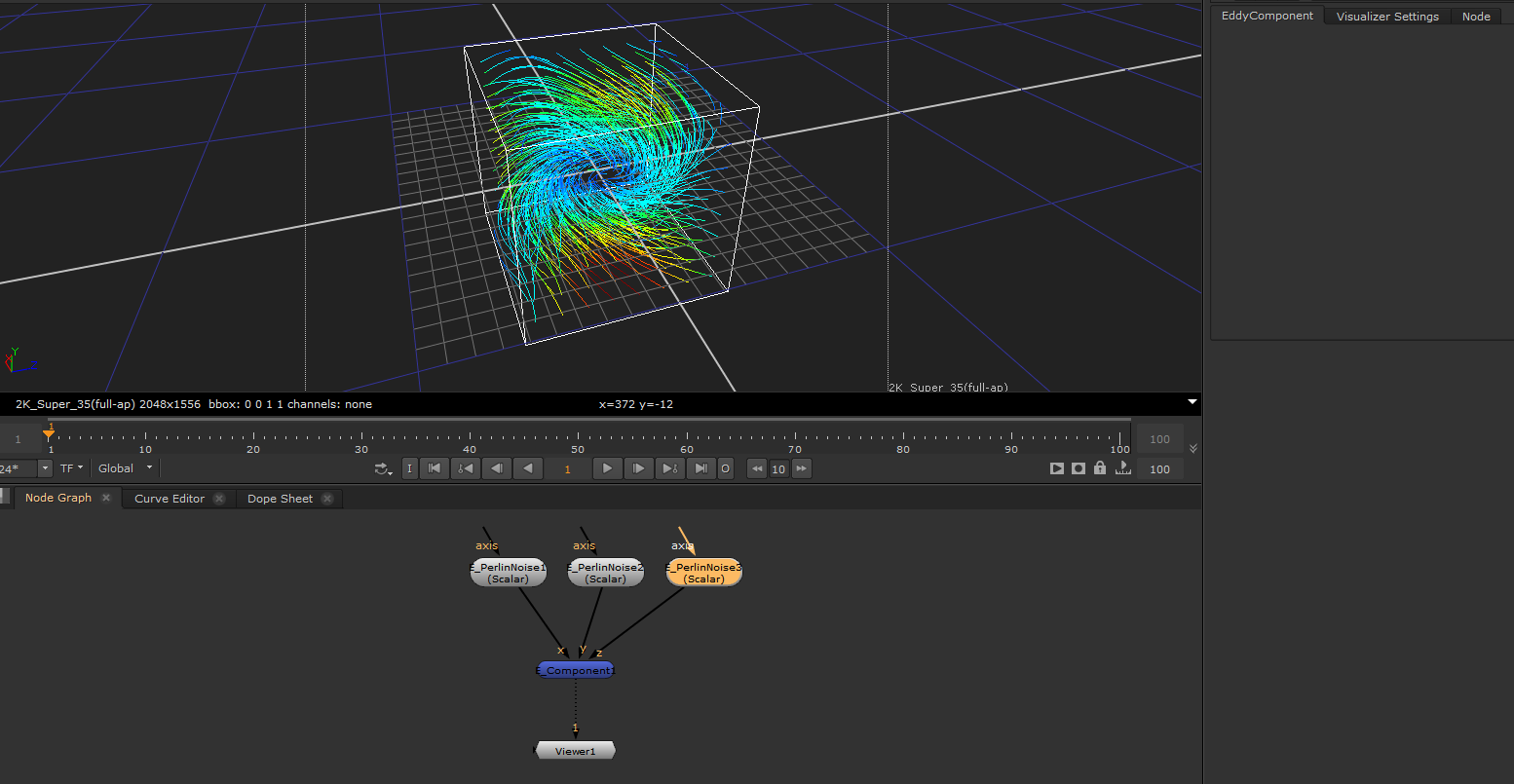
Constructing a vector channel from scalar channels¶ |
EddyDistort
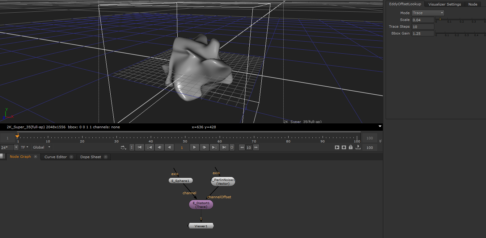
Distorts the input channel through a vector channel describing the displacement.
Usage
This node can for example be used to deform a simple geometric primitive such as a box or sphere into more complex shapes.
Note
The node’s output ValueType and Modes are determined by the ValueType of the initially connected Eddy channel and cannot be changed later.
Note
Using the Trace mode with Trace Steps is set to 1 is equivalent to direct displacement
Inputs/Outputs
Connections |
ClassType |
Number |
Description |
|---|---|---|---|
field |
EddyChannel |
1 |
An Eddy channel that will be distorted |
offset_field |
EddyChannel (vector) |
1 |
An Eddy vector channel representing the distortion |
Outputs |
EddyChannel |
1 |
A distorted version of the input channel |
Controls
Parameter |
Values |
Description |
|---|---|---|
Mode |
List |
Type of distortion applied to the input |
Vector Scale |
0…inf |
Multiplier used to control the magnitude of the distortion |
Trace Steps |
1…inf |
Maximum number of trace steps in the vector channel before the input is sampled. More steps increase the accuracy of the deformation but is more time consuming to compute. |
BBox Gain |
1…inf |
Adjusts the size change of the generated bounding box for the new output channel. A value of 0.0 will keep the input bounds. |
Modes
Mode |
Description |
|---|---|
Trace |
Starting at the current position perform one or more steps along the vector channel before sampling the input channel |
Remap Coordinates |
Sample the input channel at the UVW values (coordinates) provided by the vector channel |
Motion Blur |
Motion Blur the input channel based on the provided vector channel |
Distorting a sphere through a vector noise channel |
EddyFilter
Performs a filtering operation on the input channel. A filtering operation will appear like a blur and smooth the features of the input.
Usage
This node can be used to smooth/blur a channel.
Note
The source samples are sampled on the fly and not aggregated like in a mipmap. This means larger kernel windows will lose information of the higher detailed input.
Inputs/Outputs
Connections |
ClassType |
Number |
Description |
|---|---|---|---|
field |
EddyChannel |
1 |
An Eddy channel on which the filtering operation is applied |
Outputs |
EddyChannel |
1 |
An Eddy channel containing the result of the operation |
Controls
Parameter |
Values |
Description |
|---|---|---|
Mode |
List |
A list of the types of operations available for the input ValueType |
Kernel Width |
0…inf |
The size of the kernel window size. All the samples lie within this region. The value is specified in distance units. |
Modes
Mode |
Input ValueType |
Output ValueType |
Description |
|---|---|---|---|
Box |
Scalar/Vector |
Scalar/Vector |
Performs a 3x3x3 box filter within the kernel size window. |
Gaussian |
Scalar/Vector |
Scalar/Vector |
Performs a 5x5x5 gaussian filter within the kernel size window. |
EddyFiniteDifference
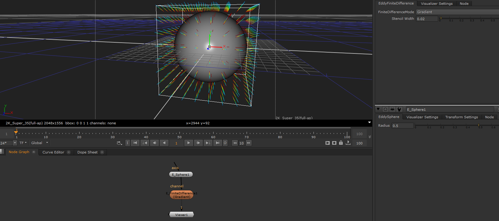
Perform finite difference operations on the input channel. A finite difference operation is an approximation of the equivalent mathematical operator - for example the gradient operator.
Usage
This node can be used to extract information and/or properties from a channel. The gradient of a signed distance channel will for example be a vector pointing in the direction of the geometric surface normal.
Note
Both the gradient and laplace operators can be used as edge detectors. The magnitude of the gradient and the value of the laplacian will peak around edges in the input data.
Note
The node’s output ValueType and Modes are determined by the ValueType of the initially connected Eddy channel and cannot be changed later.
Inputs/Outputs
Connections |
ClassType |
Number |
Description |
|---|---|---|---|
field |
EddyChannel |
1 |
An Eddy channel on which the finite difference operation is applied |
Outputs |
EddyChannel |
1 |
An Eddy channel containing the result of the operation |
Controls
Parameter |
Values |
Description |
|---|---|---|
Mode |
List |
A list of the types of operations available for the input ValueType |
Stencil Width |
0…inf |
Spacing between the samples used in the finite difference computation. This distance should ideally be around the size of the smallest feature present in the input. This would for example be the voxel size of a discrete channel. |
Note
If the feature size of the data is unknown or hard to estimate a good Stencil Width can be found manually. Start with a Stencil Width that is much smaller than the size of the bounding box of the input channel - for example the longest side of the bounding box divided by 100. Then inspect the result using the visualizer and manually adjust the Stencil Width up or down until the result contains a satisfactory level of detail.
Modes
Mode |
Input ValueType |
Output ValueType |
Description |
|---|---|---|---|
Gradient |
Scalar |
Vector |
Compute the gradient of the input channel |
Laplacian |
Scalar |
Scalar |
Compute the laplacian of the input channel |
Curl |
Vector |
Vector |
Compute the curl of the input channel |
Divergence |
Vector |
Scalar |
Compute the divergence of the input channel |
Finite difference gradient of a sphere distance channel |
EddyMask
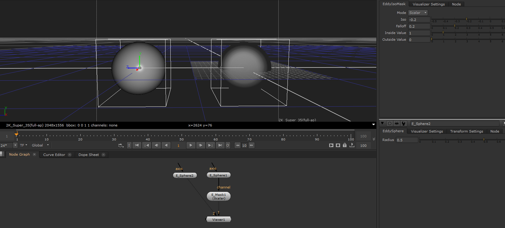
Generates a mask from a scalar channel by returning the Inside Value whenever the input channel is smaller than the Iso parameter value and the Outside Value everywhere else. This is effectively a method for classifying space into regions and assigning user specified values to these regions.
Usage
Signed distance channels in Eddy always have negative values inside and positive values outside the surface. Using an iso value of 0.0 and for example an inside value of 1.0 and outside value of 0.0 this can be used to mask out the inside of for example a sphere channel source. The resulting channel will have the value 1.0 inside the sphere and 0.0 outside.
Inputs/Outputs
Connections |
ClassType |
Number |
Description |
|---|---|---|---|
field |
EddyChannel |
1 |
An Eddy channel from which the mask will be created |
Outputs |
EddyChannel |
1 |
An Eddy channel containing the resulting mask |
Controls
Parameter |
Values |
Description |
|---|---|---|
Mode |
List |
Set the output ValueType of this channel |
Transform Type |
List |
Specifies how this vector field should behave when transformed. See Vector Channel Transformations. |
Iso Value |
-inf…inf |
Input values below this threshold are treated as “inside” |
Falloff |
0…inf |
Falloff distance in scene units between the inside / outside value. Use this to achieve a smooth transition between the inside and outside regions. |
Inside Value |
-inf…inf |
Returns this value where the input value is smaller than the iso threshold |
Outside Value |
-inf…inf |
Returns this value where the input value is larger than the iso threshold |
Using a sphere to generate a mask |
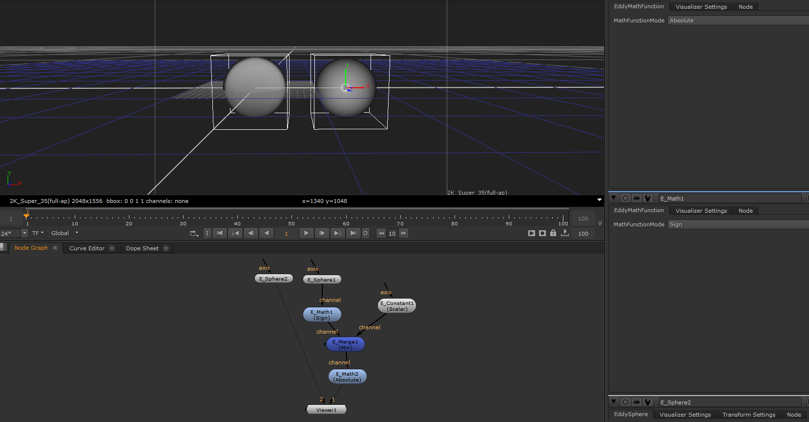
EddyMath
Perform basic mathematical operations on the input channel.
Usage
This node can be used to apply mathematical operations to change channel data - including selecting individual components of a vector channel.
Note
The node’s output ValueType and Modes are determined by the ValueType of the initially connected Eddy channel and cannot be changed later.
Inputs/Outputs
Connections |
ClassType |
Number |
Description |
|---|---|---|---|
field |
EddyChannel |
1 |
An Eddy channel on which to apply the math operation |
Outputs |
EddyChannel |
1 |
An Eddy channel containing the result of the math operation |
Controls
Parameter |
Values |
Description |
|---|---|---|
Mode |
List |
Types of math operations supported for the input ValueType |
Modes
Mode |
Input ValueType |
Output ValueType |
Description |
|---|---|---|---|
Absolute |
Scalar |
Scalar |
Returns the unsigned (i.e. absolute) value of the input |
Sign |
Scalar |
Scalar |
Return the sign of the input value ( -1.0 or 1.0 ) |
Smoothstep |
Scalar |
Scalar |
Applies a smooth step function to the input. Assumes that the input has a normalized input value range of between 0.0 and 1.0. |
Pow |
Scalar |
Scalar |
Return the second power of the input (i.e. output = input*input) |
Magnitude |
Vector |
Scalar |
Return the magnitude (i.e. length) of the input vector |
Normalize |
Vector |
Vector |
Return the normalized input vector (i.e. a vector of length 1.0) |
Vector Component X |
Vector |
Scalar |
Return the x component of the input vector |
Vector Component Y |
Vector |
Scalar |
Return the y component of the input Vector |
Vector Component Z |
Vector |
Scalar |
Return the z component of the input Vector |
Manually masking out the interior of a sphere distance channel |
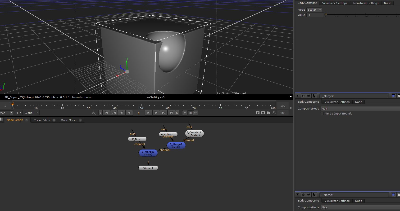
EddyMerge
Composites together multiple Eddy channel inputs.
Note
The node’s output ValueType and Modes are determined by the ValueType of the initially connected Eddy channel and cannot be changed later.
Rules apply when mixing input ValueTypes
Scalar/Scalar is allowed
Vector/Vector is allowed
Vector/Scalar is allowed
Scalar/Vector is NOT allowed
Note
To multiply a vector channel with a Scalar Mask, connect first the vector channel and the scalar channel afterwards.
Note
In some cases Scalar/Vector composites can be performed by converting the scalar channel to a vector channel using a EddyComponent node with the scalar channel as the input to all three components.
Note
For non-commutative operations (subtraction and division) the first input channel connected to the node will act as the value source and each additional channel added will subtract/divide this value.
Usage
This node can be used to merge different Eddy channels into a single channel. The manner in which the channel values are merged is controlled through the Mode parameter.
Inputs/Outputs
Connections |
ClassType |
Number |
Description |
|---|---|---|---|
fields |
EddyChannel |
1+ |
Eddy channel(s) that will be merged into a single channel |
Outputs |
EddyChannel |
1 |
The Eddy channel that is the result of the merge |
Controls
Parameter |
Values |
Description |
|---|---|---|
Mode |
List |
Type of compositing operation |
First input bounds only |
True/False |
Specifies that only the bounds of the first input should be used, otherwise all input bounds will be combined for the output. |
Modes
Mode |
Description |
|---|---|
Additive |
Adds all input channels together |
Subtract |
Subtracts each channel input (except the first one) from the value of the first channel input connected |
Minimum |
Computes the minimum value of all input channels |
Maximum |
Computes the maximum value of all input channels |
Multiply |
Computes the product of all input channels |
Divide |
Divides the first input channel with all connected channels (except the first one) |
Cutting away a sphere shape from a cube |
EddyRasterize
Rasterizes a field into a voxel grid.
Usage
This node can be used to rasterize a field into a voxel grid. If the input field was made from a large network of expensive nodes, it can be expensive to sample. The rasterized output field is faster to sample, albeit at the cost of memory and quality. Operations which require a lot of sampling (e.g. rendering) can benefit from using a rasterized field.
Inputs/Outputs
Connections |
ClassType |
Number |
Description |
|---|---|---|---|
field |
EddyChannel |
1 |
An Eddy channel that will be rasterized. |
Outputs |
EddyChannel |
1 |
An Eddy channel that contains the rasterized field. |
Controls
Parameter |
Values |
Description |
|---|---|---|
Voxel Size |
0…inf |
The size of the voxels to use. This has a big effect on memory usage and quality. |
Interpolator |
List |
The interpolator to use when sampling the rasterized voxels. See Interpolators for more details. |
EddyRemap
Remaps the value ranges of the input channel.
Note
The node’s output ValueType and Modes are determined by the ValueType of the initially connected Eddy channel and cannot be changed later.
Usage
This node can be used to remap the value range of the input channel to another user defined range. For example to the interval 0..1 for use as an alpha mask.
Inputs/Outputs
Connections |
ClassType |
Number |
Description |
|---|---|---|---|
field |
EddyChannel |
1 |
An Eddy channel that will be remapped |
Outputs |
EddyChannel |
1 |
An Eddy channel that contains the result of the remapping operation |
Controls
Parameter |
Values |
Description |
|---|---|---|
Ramp |
Ramp |
Control the remapping via Nuke’s ramp widget |
Clamp |
True/False |
Specifies if the result should be clamped to 0…1 |
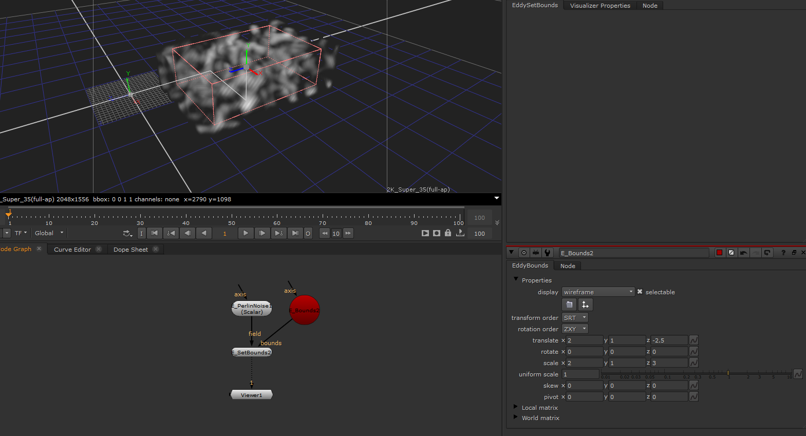
EddySetBounds
Assigns new bounds to the input channel.
Usage
This node can be used to change the bounds on a channel. Usually the bounds on a field are determined automatically, but in cases where the automatic bounds are not good enough for some reason, this node allows the bounds to be set manually.
Note
The bounds of a channel cannot be used to perform clipping or masking on the values in the channel. Instead the bounds should be thought of as defining the ‘interesting’ region of the channel. Channels can and do have values defined outside of the bounds. For example, an emitter uses the bounds to determine where to emit, however this is not always exact so values from just outside the bounds may be emitted also. Use compositing operations to mask out regions correctly.
Inputs/Outputs
Connections |
ClassType |
Number |
Description |
|---|---|---|---|
field |
EddyChannel |
1 |
An Eddy channel that will have its bounds changed |
bounds |
EddyBounds |
1 |
The new bounds for the channel |
Outputs |
EddyChannel |
1 |
An Eddy channel that contains the input channel with the new bounds |
Setting the bounds of a Perlin noise channel |
EddyTransformField
Applies an axis transformation to a channel.
Usage
This node allows a channel to be transformed by an axis node. While most channel nodes have axis inputs, sometimes it is more convenient to apply the transformation later in the graph, for example to transform a channel which was composited from many inputs.
Inputs/Outputs
Connections |
ClassType |
Number |
Description |
|---|---|---|---|
field |
EddyChannel |
1 |
An Eddy channel that will be transformed |
axis |
axis |
1 |
An axis node to provide the transformation |
Outputs |
EddyChannel |
1 |
An Eddy channel that has been transformed by the axis |
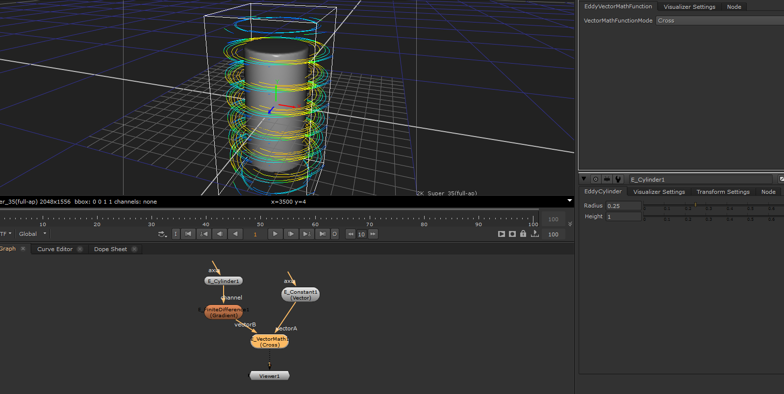
EddyVectorMath
Perform vector math operations on two input channels.
Usage
This node is used to apply vector math operations to Eddy vector channels.
Inputs/Outputs
Connections |
ClassType |
Number |
Description |
|---|---|---|---|
fieldA |
EddyChannel |
1 |
The first Eddy vector channel of the vector math operation fieldA OP fieldB |
fieldB |
EddyChannel |
1 |
The second Eddy vector channel of the vector math operation fieldA OP fieldB |
Outputs |
EddyChannel |
1 |
An Eddy vector channel that is the result of the vector math operation |
Controls
Parameter |
Values |
Description |
|---|---|---|
Mode |
List |
Types of math operations supported for the input ValueType |
Modes
Mode |
Input ValueType |
Output ValueType |
Description |
|---|---|---|---|
Dot |
Vector |
Scalar |
Return the dot product of the two vectors |
Cross |
Vector |
Vector |
Return the cross product of the two vectors |
Using vector math to calculate trajectories around a cylinder |
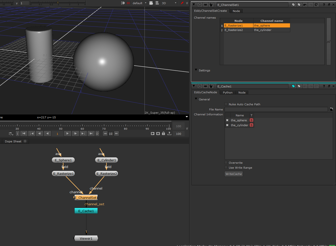
EddyChannelSet
Combines multiple fields into a channel set.
Usage
This node combines multiple input channel sets and fields into a single result channel set. Channel names can be provided for the fields included in the channel set. If an individual channel input is given the same name as a pre-existing channel in an input channel set, then it will replace that channel in the result.
Inputs/Outputs
Connections |
ClassType |
Number |
Description |
|---|---|---|---|
channel |
EddyChannelSet/EddyChannel |
0+ |
Channels and/or channel sets which will be combined into the channel set result. |
Output |
EddyChannelSet |
1 |
Channel set containing all of the input channels. |
Controls
Parameter |
Values |
Description |
|---|---|---|
ChannelNames |
ListViewWidget |
Allows channel names to be specified for the input channels. By default, the channel will be given the same name as the input node. |
Combining some rasterized fields into a ChannelSet so they can be written to a cache. |
EddyFieldDebug
Allows numeric value visualization of Eddy Fields.
Usage
This node can be used to inspect the numeric values of any Eddy field. It works both for scalar and vector fields and can be useful to debug complex field compositing operations.
Inputs/Outputs
Connections |
ClassType |
Number |
Description |
|---|---|---|---|
channel |
EddyChannel (Scalar/Vector) |
1 |
Scalar channel that will be used to drive the field debug node. |
Controls
Parameter |
Values |
Description |
|---|---|---|
Enable Visualizer |
True/False |
Enables drawing. |
Resolution |
1…512 |
Number of samples along the dominant axis of channel bounding box. |
Width |
0…inf |
Multiplier for the channel bounding box or overall width when bounds aren’t provided. |
Draw Bounds |
True/False |
Enable drawing of the bounding box wireframe. |
Draw Subbounds |
True/False |
Enable drawing of the active space wireframe for sparse channels. |
Numeric Text Color |
(0,0,0)…(inf,inf,inf) |
The color of the numeric text. |
Text Scale |
0…inf |
Scales the size of the text. |
Numeric Precision |
1…inf |
The floating point precision. Controls the maximum number of digits displayed after the decimal separator. |
Scientific Notation |
True/False |
Use scientific notation to display floating point numbers. |
Draw Background |
True/False |
Adds a background behind each text to make the text more readable. |
Background Color |
(0,0,0)…(inf,inf,inf) |
The color of the background area behind the text. |
Display Values In Range |
True/False |
Only values that are within the range specified will be displayed. For vector values the magnitude is used to check the range. |
Minimum Value Range |
-inf…inf |
Minimum range of the values that will be displayed. |
Maximum Value Range |
-inf…inf |
Maximum range of the values that will be displayed. |
Crop Window |
True/False |
Enable GL corner points to adjust the visualizer draw region. |
Reset Crop |
Button |
Reverts the crop window to the original bounding box from the channel. |