Channels (fields)
Channels (also referred to as fields or volumes) are 3D volumes filled with values that represent specific physical properties - for example pressure, velocity, distances, or smoke density. Channels can either be implicit, where the value at each point comes from a mathematical function (e.g. the SphereRefLabel node), or discrete, where the values are interpolated from a 3D grid of values (e.g. simulation elements, loaded caches).
Channels can be visualized or rendered directly in Nuke and can also be exported and imported as OpenVDB volumes for later processing in Eddy or other tools.
Scalar Channels
Scalar channels store one floating point decimal value at each point in space. Examples of simulation scalar channels are temperature, pressure and density.
Signed Distance Channels
Signed Distance Channels (often referred to as Signed Distance Fields, or SDFs) are a type of channel that can be used to represent a surface.
The SDF is an implicit geometric representation where the surface of the geometry is indirectly given by each point in space storing the signed distance to the closest point on the surface of the geometry. Though a seemingly excessively complex geometric representation SDFs have several properties that allow for very fast geometric deformation and collision detection which makes them well suited for simulation.
In Eddy SDFs can be generated from meshes using for the Eddy Mesh to Volume node and from particles using the Particle to Volume node. The simple shape channel nodes (e.g. SphereRefLabel, BoxRefLabel) also output SDF channels.
Note
Eddy uses the convention that SDFs have negative values inside the surface of the geometry and positive outside.
Note
When visualizing a modified/distorted SDF channel Eddy may not automatically be able to determine that the channel should be visualized as a surface. In that case you need to tick the ‘Force SDF’ checkbox to tell Eddy to interpret the data as an SDF geometry.
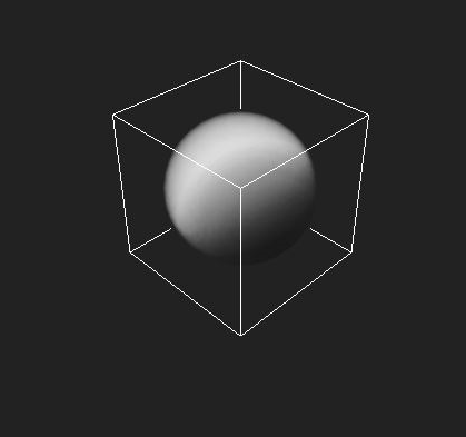
Scalar channel visualized as a fog volume¶ |
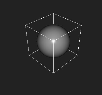
Signed distance channel¶ |
Vector Channels
Vector channels store three floating point decimal values at each point in space. Examples of vector channels are velocity, vorticity, or color.
Vector Channel Transformations
When a vector channel is transformed (e.g. rotated or scaled) the value of the vector at each point can need to be transformed also. For example rotating a velocity channel should also rotate the direction of the velocity values themselves. Nodes will determine the transformation type automatically if possible, but sometimes it must be manually specified or can be overridden.
There are three ways of transforming a vector channel:
Vector: This is the default transformation type. The vector value is rotated and scaled by any applied transformation. Velocity, force, and direction channels should all transform with this method.
Normal: Normal vectors are affected by rotations in the same way as regular vectors, but they behave differently when scaled. This is used for normal vector channels that are voxelized from meshes by the MeshToVolumeRefLabel node, or for the gradient calculated by the FiniteDifferentRefLabel node.
Coordinate: Coordinate vectors are not affected by transformations. This should be used for color channels, texture coordinate channels etc.
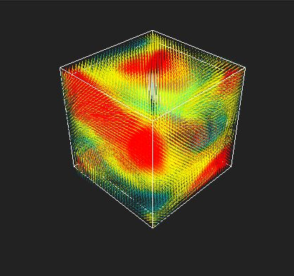
A vector channel¶ |
Channel Sets
An Eddy Channel Set is simply a collection of channels, where each channel has been given a name. Channel Sets are output from various nodes that produce multiple channels, such as elements, cache loaders, or voxelizers.
To extract an individual channel from a Channel Set, use the E_Channel node.
Channel Set Widget
The Channel Set widget appears in most of the property panels of nodes that output Channel Sets. It allows some of the properties on the individual channels to be specified, as well as adding default channel definitions. This is the widget as it appears on an E_CacheLoader node:
The Channel Set widget as it appears on an E_CacheLoader |
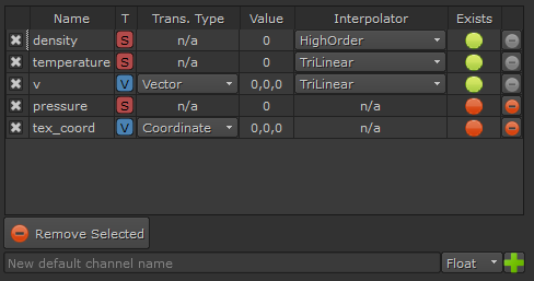
Different nodes will display different columns, depending on what is appropriate for the node.
The selection checkbox controls whether or not this channel will be present in the output channel set.
Name: Name of the channel. This is what must be specified in the E_Channel node to extract the individual channel.
T: The type of the channel, i.e. scalar or vector.
Trans. type: The transformation type of the vector channel. See Vector Channel Transformations.
Value: The default value of the channel.
Interpolator: The interpolator to use when sampling a discrete channel.
Exists: Indicates if the channel exists in the cache being loaded. Channels that don’t exist in the cache will be replaced with a default channel.
New default channels can be added to the widget by entering the channel name in the text box at the bottom of the widget, selecting the type of the new channel, and clicking the plus icon.
Interpolators
Channels which sample their values from a discrete 3D grid need to specify an interpolator, which describes how adjacent values in the grid are combined to produce the final value.
Trilinear: This is the simplest and fastest interpolator. It is the default and is the recommended safe choice.
B-Spline: This is a type of tricubic interpolator which is slightly faster than the other tricubic interpolators, but introduces a lot of smoothing to the channel.
Tricubic: This is standard tricubic interpolation. The method is slower than trilinear but produces a smoother result without the excessive smoothing of B-Spline. Tricubic can overshoot data.
Monotonic tricubic: This is a version of tricubic interpolation that is monotonic and thus will not overshoot data.
High order: This is an Eddy custom high order interpolator. It is faster than Tricubic and produces results smoother than trilinear but not as smooth as Tricubic. This method typically does not overshoot data.
Clamped high order: This is a version of the High order interpolator that sacrifices some smoothness in order to guarantee that it never overshoots data.
Note
Interpolation attempts to estimate values in the space in-between known data points. This is an approximation as the ‘real’ values at these locations are not known. Thus the choice of interpolation method can subtly affect the perceived quality of the data. Trilinear is a good conservative choice and is thus the default. Perceived quality improvements can be achieved by using other interpolation methods but typically at a the cost of increased computation time.
Note
The interpolation mode affects the speed and perceived quality of any node that uses the channel as an input, for example the shader node and thus rendering.
Choosing Interpolation Method
The most appropriate interpolator to use is unfortunately problem dependant, however as a rule-of-thumb use Trilinear unless you need to ensure a smooth result - in which case we recommend our High order method. If trilinear gives unsatisfactory results and High order is too slow then B-Spline, Tricubic or Monotonic tricubic can provide a compromise between speed and quality.
Interpolation Overshoots
Non-linear interpolators risk overshooting or undershooting data. This means that when estimating the value between two known data points with for example the values 0 and 1 the estimated value can be below 0 or above 1 - i.e. a value that lies outside the value interval being interpolated. This phenomenon happens in regions where the values of the data being interpolated changes rapidly and can be problematic. If the value being interpolated describes density for example the interpolation can produce values below 0 which would be invalid in this context.
Likewise when interpolating SDF channels interpolation methods that overshoot may distort the geometry near sharp geometric features like corners.
For this reason it is recommended to use an interpolation method that does not overshoot for cases like this. Either Tricubic if smoothness is not a primary concern or our high order method if smoothness is important. If smoothness is paramount B-Spline or Monotonic tricubic are the best options.
Bounding Box
All channels provide axis aligned bounding box information. This can be either a single AABB or an array of non-overlapping AABBs describing the bounded region each volume represents.
Note
For script access all nuke channel nodes holds two hidden attributes (btn_field_bounds, field_bounds) enabling access to this information. Upon pressing the “btn_field_bounds” button knob, the Box3 “field_bounds” knob stores the result of the query. In the case of undefined or infinite bounds, an inverted bounding box is returned.
Compositing Operations
TODO: Examples of masking, inverting masks, min/max, add/sub
SDF Compositing
TODO: Examples of min/max SDF behavior