Render Settings
Sampling
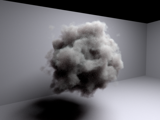
The main setting to control rendered image quality is the ‘Maximum samples’ setting. This controls how many samples are taken for each pixel in the image, also known as ‘camera’ samples. The random samples are averaged together to produce the final pixel, so the more samples that are taken the closer the pixel color gets to the true result.
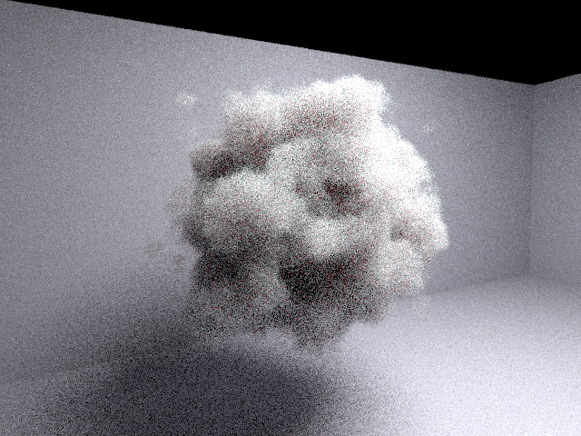
Image rendered with just 10 camera samples (note volume samples have been reduced in this and other later images for illustrative purposes).¶ |

Image rendered with 200 camera samples.¶ |
Note
Path tracing uses Monte Carlo integration to determine the color of each pixel. Monte Carlo integration takes many cheap noisy samples for each pixel and combines them to find the final pixel color. This random noisy sampling means that the final image will also have noise if not enough samples are taken. The noise error in an image is inversely proportional to the square root of the number of progressions. This means that in order to reduce the error by half, four times as many progressions must be used.
Adaptive sampling
Eddy uses adaptive sampling by default. This means that the renderer will stop generating samples for a pixel once it has reached a required error threshold. This allows the render to finish quicker and focus its effort on the areas of the image where it will be most beneficial.
Adaptive sampling is controlled by the ‘Adaptive error bound’ setting. This specifies the error threshold for each pixel - once a pixel has less error than this it will no longer be sampled. Increasing the error bound will make the renderer complete faster but potentially have more noise overall, reducing the error bound will lower the overall noise level but will take longer.
Tip
The error bound can be set to zero to disable adaptive sampling.
To see what the adaptive sampling is doing, the ‘sample_count’ AOV can be used to see exactly how many samples are taken for each pixel.

Image rendered with 1000 samples and an error threshold of 0.05.¶ |
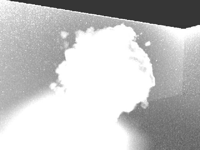
Sample count AOV for left image. The volume and the indirect lighting from the volume in its shadow use the most adaptive samples.¶ |

Image rendered with 1000 samples and an error threshold of 0.1. Render is about 50% faster than above.¶ |
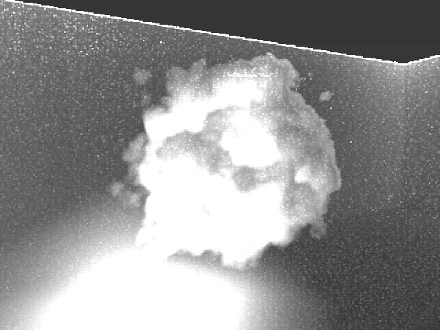
Sample count AOV for left image. Less samples used for directly lit parts of the volume.¶ |
Advanced sampling settings
The advanced sample settings control how many samples of different types are taken by each camera sample. If the noise in an image is coming from a particular source, increasing the number of samples for that source only can reduce the noise without taking unnecessary samples elsewhere.
Note
The advanced sample counts are multipliers for the camera samples. They specify how many samples should be taken by each camera sample. Therefore they should generally not be set too high, perhaps around 20 samples should be the limit. They should be thought of as controlling the ratio between the different sample types - the camera samples should still be used to control the overall quality. Camera samples also benefit from adaptive sampling.
Tip
To figure out which sample types to increase, you must first find out where the noise is coming from. Using AOVs the image can be split into its separate components, and the noise can be examined in each. Alternatively setting the ‘ray depth’ to 1 will render direct lighting only, helping to show whether noise is coming from direct or indirect lighting.
Warning
The advanced sampling settings can interact in a surprising way with the clamping in some scenes. If the noise seems to increase when the advanced sample counts are increased, clamping could be the culprit. See Clamping for more information.
Direct light samples
The direct light samples controls how many light samples are taken on surfaces. Noise from direct lighting can be due to area lights or environment lights, or due to volume shadows. To see if there is noise from direct lighting render the image with ray depth set to 1 to disable all indirect lighting.
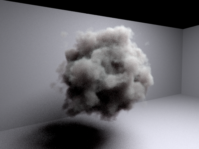
Image rendered with 100 samples and ray depth of 1, to see the direct lighting only.¶ |
Direct lighting samples increased from 1 to 10. The noise on the ground and walls in reduced, the volume is unchanged.¶ |
Volume samples
The volume sample count determines how many points inside the volume are sampled for direct lighting. Noise for volume direct lighting can come from area lights or environment lights, or can also be due to the volume itself. To see if there is noise from direct lighting render the image with ray depth set to 1 to disable all indirect lighting.
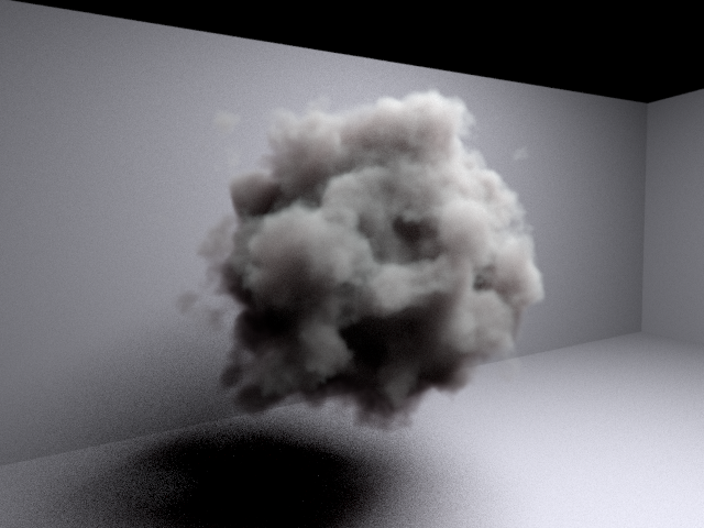
Image rendered with 100 samples and ray depth of 1, volume samples increased to 10. Compare to above, volume noise is reduced, ground noise is unchanged.¶ |

Both volume samples and direct light samples increased to 10. Both volume noise and ground noise is reduced. Note that multiplying camera samples by 10 would have had the same effect.¶ |
Volume indirect samples
The volume indirect sample count determines how many secondary ray samples are taken inside the volume to calculate the indirect lighting. To see if indirect lighting is the source of noise in the image, the ‘indirect’ AOVs can be used, or the image can be compared to one with ray depth set to 1 which does not include indirect lighting.

Ray depth increased to 5 to include indirect lighting. Direct light and volume samples are still increased to 10, so additional noise in this image compared to the previous image is due to indirect lighting.¶ |
Volume indirect samples increased to 10. Note the volume noise is now reduced, but the surface indirect lighting (in the shadow) is still noisy.¶ |
Indirect samples
The indirect sample count determines how many secondary ray samples are taken at each surface point. To see if indirect lighting is the source of noise in the image, the ‘indirect’ AOVs can be used, or the image can be compared to one with ray depth set to 1 which does not include indirect lighting.

Indirect samples increased to 10, volume indirect samples left at 1. The indirect light on the ground in the shadow is now reduced, the volume noise is unchanged.¶ |

Both indirect samples and volume indirect samples increased to 10. Both volume noise and ground noise are reduced. Note that multiplying camera samples by 10 would have had the same effect.¶ |
Indirect sample sub-types
There are four indirect sample sub-types. These are used to control the number of indirect samples for particular types of indirect sampling at surfaces:
Indirect diffuse samples: Diffuse indirect lighting on diffuse surfaces.
Indirect reflection samples: Glossy reflections from surfaces.
Indirect refraction samples: Glossy refractions from surfaces.
Indirect subsurface samples: Subsurface scattering samples, i.e. diffuse refractions.
Note
Increasing the ‘indirect samples’ will increase the samples for all indirect sub-types. It is not necessary to increase all the sub-types sample counts individually. Adjusting the sub-types is only necessary if some sub-types should be sampled more than other sub-types.
Tip
Using an indirect sub-type can avoid unnecessarily taking more samples on other sub-types. For example, in a scene with both glossy and diffuse reflecting surfaces, increasing the indirect reflection samples to 10, while leaving the general indirect sample count at 1, will take 10 samples only on the glossy surfaces, leaving the diffuse surfaces with just 1 sample.
Note
The ratio between the different indirect sub-types will always be respected. For example, setting the general indirect samples to 10 and the indirect reflection sub-type to 2 samples will still take 10 indirect samples on the surface, however it will take twice as many reflection samples than the other sub-types. The sub-type sample counts also allow fractional values for this reason.
Ray depth
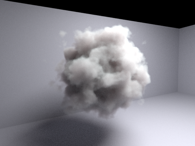
The ‘Maximum ray depth’ settings controls how many bounces are allowed in a path from the camera to a light. A maximum depth of 1 will allow direct lighting only, larger values will include more indirect lighting. The maximum ray depth can have a significant impact on how long volume rendering takes, however it is very important for the appearance of some volumes with a high albedo, e.g. clouds. The ray depth can also be set to -1 for an unlimited depth, however after a certain depth there will be diminishing returns in terms of new indirect light being added to the image.

Maximum ray depth of 1, allows only direct lighting.¶ |
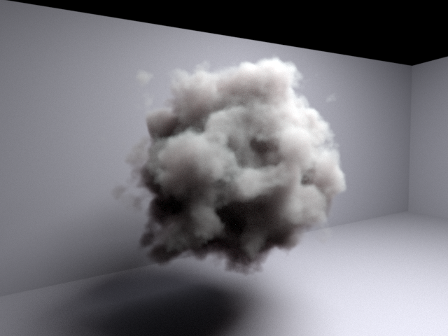
Maximum ray depth of 2, some indirect lighting.¶ |

Maximum ray depth of 5, most indirect lighting is now included.¶ |

Maximum ray depth of 10, only slightly more indirect lighting than a depth of 5.¶ |
Volume settings
Automatic and manual settings
By default Eddy will attempt to choose appropriate volume settings automatically. It will analyze the volume to decide what type of integrators to use, and what type of emission if any is used by the volume. If the chosen automatic settings are not ideal, or more customization is desired, the volume settings can be specified manually instead.
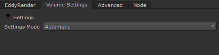
Automatic settings enabled.¶ |
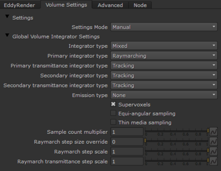
Manual volume settings.¶ |
Integrators
There are three categories of integrators available to be selected. The actual integrators used internally by Eddy are advanced specializations, but these categories capture their main features.
Raymarching: These integrators work by stepping along the ray, sampling the volume at each step. The voxel size is used as the step size. These integrators are high quality, but can be expensive due to the large number of volume samples required.
Tracking: These integrators work by taking random length jumps along the ray. Usually they will take less steps than the raymarching integrators, which makes them faster. However the additional randomization means they are usually lower quality too. No fixed step size is required, so these integrators work with implicit volumes.
Delta tracking: A variation of tracking integrators for transmittance rays only. Possibly slightly faster but also noisier. Rarely needed, tracking is usually fine.
Note
Raymarching integrators need to know the step size. For most volumes this is the voxel size, but implicit volumes may not have a voxel size available. The ‘Raymarch step size override’ setting must be used in this case. See Implicit Volume Rendering for more details.
Some general tips for choosing the integrators:
For low camera sample counts, raymarching integrators can be better as they are less noisy. Tracking integrators can be more suitable for higher camera sample counts, the additional noise is compensated by the higher sample count, and the improved performance of the tracking integrator can be felt.
Secondary rays should usually use tracking integrators instead of raymarching integrators. A larger number of secondary rays will be required anyway to resolve the indirect lighting, so the additional noise from tracking is less of an issue and the improved performance of tracking is very beneficial for the secondary rays.
Transmittance integrators can usually be set to tracking. For low sample counts, raymarching may be better.
Small volumes with low voxel counts can often work best with raymarching integrators. Less voxels means less raymarching steps, and GPUs can be very efficient at sampling volumes.
Supervoxels
Supervoxels are a hierarchical acceleration structure, used to speed up volume integration. They are especially beneficial for large volumes that contain empty space, regions with constant density, or volumes that have a wide variety of densities. Supervoxels allow raymarching integrators to skip empty space, and for tracking integrators to take larger steps in lower density regions.
For small volumes that already fit their bounding box well, supervoxels may not provide a significant benefit. Disabling supervoxels for these volumes can reduce overhead and improve performance slightly.
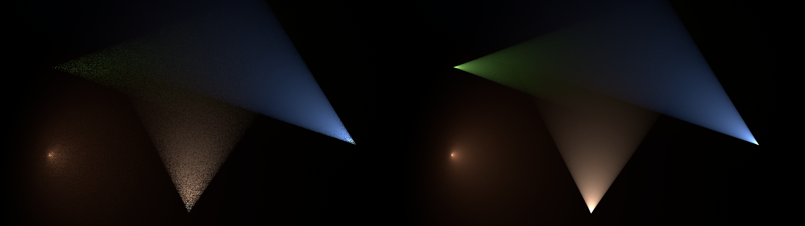
Equi-angular sampling
When bright lights are embedded deep within a dense fog volume, the standard sampling methods can be very noisy as they may not take enough samples close to the lights, instead concentrating their samples closer to the surface of the volume facing the viewer. Equi-angular sampling is a technique to help this, which will take more samples near to the light when the camera ray passes close to the light.
Spot lights embedded in a dense fog volume. On the left is the standard tracking sampler, on the right is the equi-angular tracking sampler. |
Thin media sampling
When the volume is optically thin (i.e. very transparent), the standard tracking samplers can be noisy as most of the rays will pass straight through the volume without colliding. The thin media sampling mode can be enabled in the tracking integrators to improve this, it will distribute samples throughout the volume regardless of the volume density.
Clamping
Clamping is a method to reduce noise by putting a limit the contribution of each sample to the pixel. These large contributions can be a significant source of noise so clamping them removes the noise from the image.
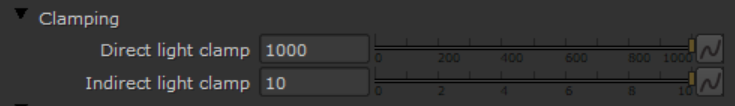
Clamping limits.
There are two clamping limits - one for direct light contributions, and one for indirect light contributions. Clamping the direct and indirect separately is helpful because the indirect is usually a more troublesome source of noise, but it can also be more aggressively clamped without introducing too many artefacts, therefore the indirect clamping limit can be set much lower than the direct clamping limit.
Note
While clamping is useful, it is a non-physical effect which will remove light from the scene. The large contributions which are removed may be noisy, but with enough samples they would still eventually converge and brighten the image. With clamping these parts of the image will never reach their full brightness.
Tip
Clamping can be disabled by simply setting the limits to very high numbers. Alternatively all AOVs have an option to disable clamping.
Warning
The values chosen for the clamping limits are dependent on both the scene itself and the way it is sampled. For example, surfaces with a noisy BRDF will generate more noisy sample contributions, so more of these samples will be clamped. Similarly the Advanced sampling settings can affect the clamping. Counter-intuitively, increasing the number of samples can increase the noise in an image. The higher number of samples reduces the noise in each sample contribution, which then means they are less likely to be clamped, so the overall image will get brighter and possibly noisier.
Pixel filters
The pixel filter specifies how the camera samples are combined into the final color for the pixel. It controls the anti-aliasing of the image as well as the sharpness or blurriness of the image.
The filter width controls the size of the area over which camera samples are taken for each pixel. Larger values will make the image more blurry, smaller values will make the image sharper. Typically it should be in the range 1-5, it should cover at least one pixel but not too much further.
There are multiple pixel filter functions available. The default is Gaussian which is a safe choice. We recommend either Gaussian or Blackman-Harris. The others are provided mainly for reference, using them should be a special case as they can have drawbacks. Remember that reducing the filter width will also reduce blurriness for all filter types, so using one of the sharpening filter types to reduce blurriness is not required.
Box: The simplest filter function, just averages the samples together. Also the worst quality.
Triangle: Better than the box filter, but not the best quality either.
Gaussian: The Gaussian filter function provides good results in practice, although with some blurring. This is the default filter.
Blackman-Harris: Very similar to the Gaussian, but with slightly less blurring. Also a good choice.
Mitchell-Netravali: A sharpening filter which attempts to reduce blurring without introducing artefacts. Note that since this is a sharpening filter it can introduce ringing artefacts into the image. Also beware of sharpening the noise in your image!
Lanczos: A sharpening filter, also known as a sinc filter. Sharpens a lot more than the Mitchell filter, but also introduces a lot more artefacts. Not recommended in practice, use the Mitchell filter if you must have a sharpening filter.