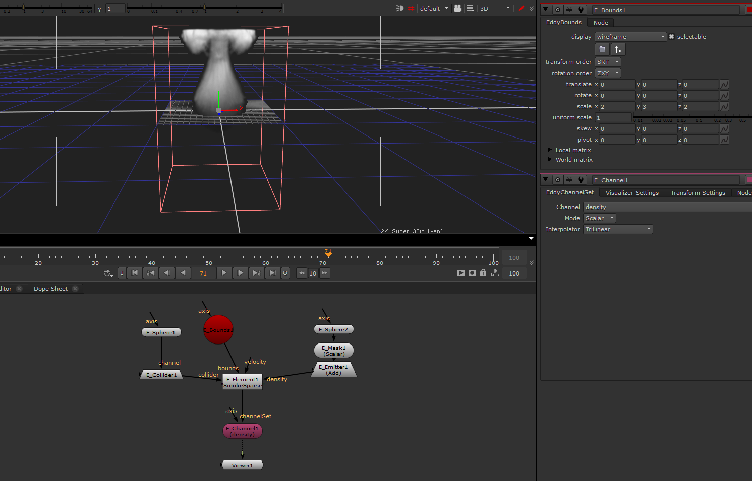
E_Bounds
Defines a bounded region of space.
Usage
This node can for example be used as input to an E_Element node to bound the extent of an adaptive sparse simulation preventing the simulation from growing beyond the selected bounds.
Inputs/Outputs
Connections |
ClassType |
Number |
Description |
|---|---|---|---|
axis |
axis |
0-1 |
A Nuke axis node representing a transformation applied to the bounded region of space |
Output |
EddyBounds |
1 |
Eddy bounds |
Controls
Parameter |
Values |
Description |
|---|---|---|
Transformation |
Transform |
Transform parameters describing the shape and extent of the bounded region as a transformed unit cube |
Bounding a sparse smoke simulation using the E_bounds node |
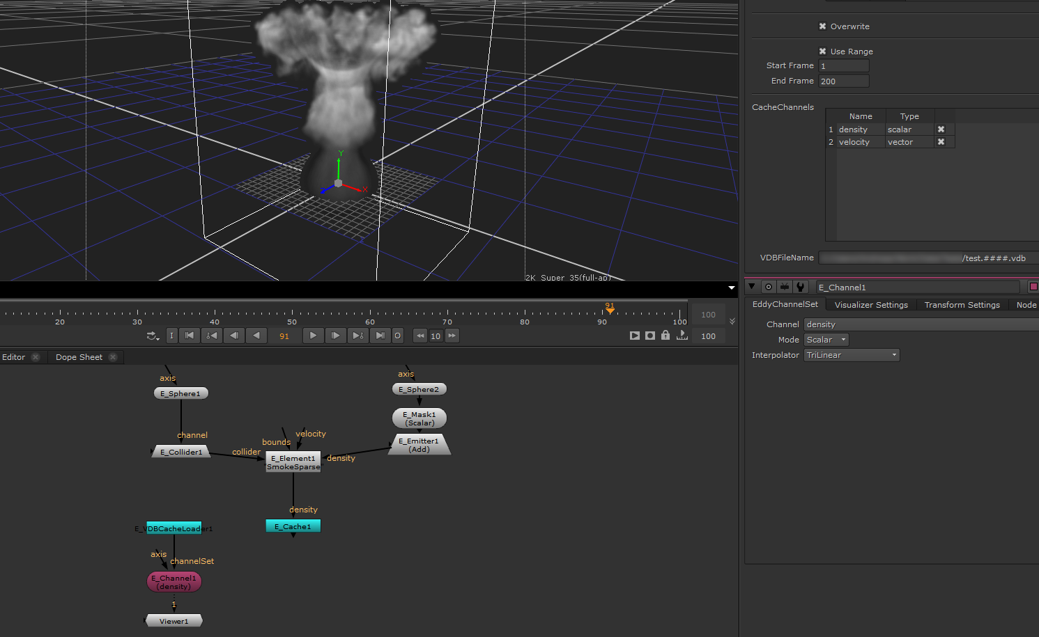
E_Cache
Writes a set of Eddy channels in the OpenVDB file format, and loads back previously saved caches when scrubbing the timeline.
Usage
This node can for example be used to cache the frames from an Eddy simulation to file - allowing the data to be used later for rendering or interaction with another simulation. To cache out a sequence press the WriteCache button on the node, select the desired frame range and press ‘ok’.
It also enables an interactive workflow. When a simulation is being cached, this node will load the previously saved cache when trying to view a frame earlier than the current simulation time. Without the E_Cache node, the output of an E_Element simulation will always be the latest simulated frame, regardless of the current frame in the timeline.
Inputs/Outputs
Connections |
ClassType |
Number |
Description |
|---|---|---|---|
channelSet |
EddyChannelSet |
1 |
An Eddy channel set containing channels that will be cached to a file |
Output |
EddyChannelSet |
1 |
Either the same Eddy channel set as is the input to this node, or a previously cached channel set if an earlier frame is requested. |
Controls
Parameter |
Values |
Description |
|---|---|---|
Nuke Auto Cache Path |
True/False |
Enable automatic Nuke caching of channel set data |
File Name |
Filename |
The nuke style filename (including file path) to which the cache should be written |
Channel Information |
Multiselect list |
A list of all channels avaliable in the input channel set. The selected channels will be written to the cache. See Channel Set widget. |
Overwrite |
True/False |
Controls whether the cache node is allowed to overwrite existing files or not |
Use Write Range |
True/False |
If enabled the cache node will only write frames from the interval between Start Frame and End Frame |
Write Range Start Frame |
-inf…inf |
First frame that will be cached |
Write Range End Frame |
-inf…inf |
Last frame that will be cached |
Note
Use the ‘#’ character to automatically enumerate cache files. myfile.#.vdb will result in files myfile.1.vdb, myfile.2.vdb etc. and myfile.####.vdb will result in files myfile.0001.vdb, myfile.0002.vdb etc.
Note
Only voxel-based channels can be saved to VDB. Attempting to save an implicit field will result in an error. Use RasterizeFieldRefLabel and ChannelSetRefLabel to convert an implicit field to a voxel-based field and combine it back into a channel set for writing.
Caching a sparse smoke simulation to disk using an Eddy cache node |
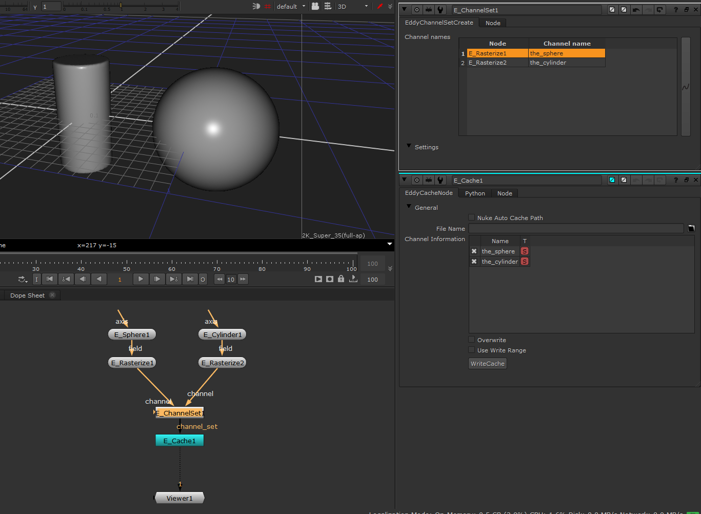
E_ChannelSet
Combines multiple fields into a channel set.
Usage
This node combines multiple input channel sets and fields into a single result channel set. Channel names can be provided for the fields that are being included in the channel set. If an individual channel input is given the same name as a pre-existing channel in an input channel set, then it will replace that channel in the result.
Inputs/Outputs
Connections |
ClassType |
Number |
Description |
|---|---|---|---|
channel |
EddyChannelSet/EddyChannel |
0+ |
Channels and/or channel sets which will be combined into the channel set result. |
Output |
EddyChannelSet |
1 |
Channel set containing all of the input channels. |
Controls
Parameter |
Values |
Description |
|---|---|---|
ChannelNames |
ListViewWidget |
Allows channel names to be specified for the input channels. By default the channel will be given the same name as the input node. |
Combining some rasterized fields into a ChannelSet so they can be written to a cache. |
E_Collider
The collider node represents collision objects in the simulation space with which an Eddy simulation element can interact. Each collider is made up of a Signed Distance Channel (SDC) representing the collision object geometry and a velocity vector channel representing the object motion.
Usage
This node is used to define collision objects with which an Eddy simulation element can interact.
Note
The collision geometry should ideally be as close to signed distance data as possible but Eddy can collide against any signed scalar channel with a negative inside and positive outside sign convention. Poor distance channel properties may however result in reduced quality of boundary interactions.
Note
The velocity data of a collider must match the motion of the geometry as closely as possible. Errors in velocity input will result in poor or improper interactions with collision objects. For objects where the motion is defined through an animated transform the E_Velocity node can be used to automatically compute its velocity channel.
Inputs/Outputs
Connections |
ClassType |
Number |
Description |
|---|---|---|---|
channel |
EddyChannel (Scalar) |
1 |
Scalar channel representing the collision geometry by the sign convention that negative values mark interior regions and positive values mark exterior regions. Should ideally be a Signed Distance Channel |
vel |
EddyChannel (Vector) |
0-1 |
Velocity of the collision object. If not provided the collision object is assumed to be static |
Output |
EddyCollider |
1 |
Collision object for use with simulation Elements |
Controls
None
A sparse smoke element smoke plume with an additive sphere emitter and a stationary sphere collider |
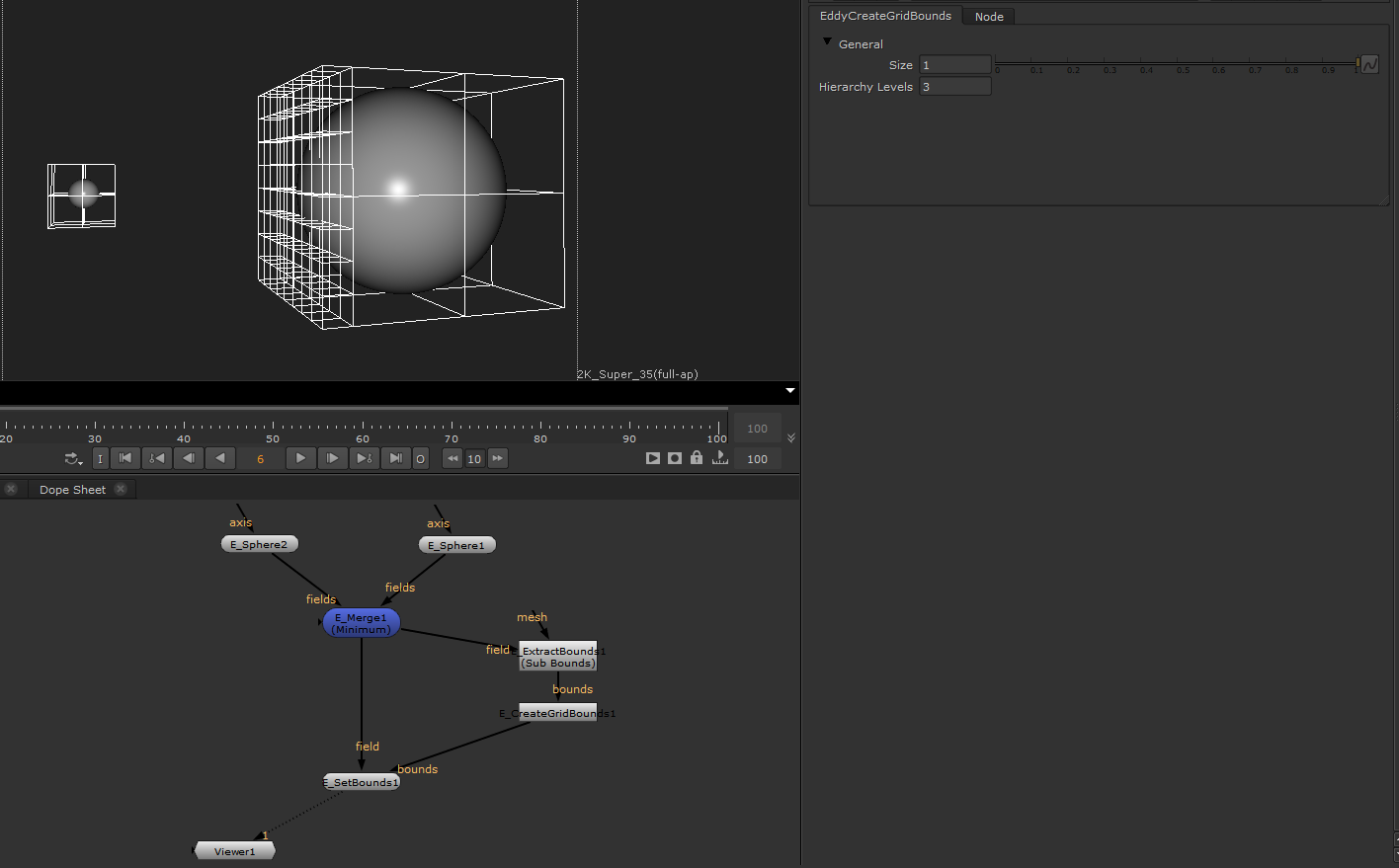
E_CreateGridBounds
The CreateGridBounds node allows to refine or coarsen a single or a collection of bounding boxes.
Usage
The node will process each bounding box and fill it with uniform bounding boxes determined by the size parameter. When the number of Levels is non zero, the node will attempt the coarsen areas as much as possible to reduce the overall number of bounding boxes.
Inputs/Outputs
Connections |
ClassType |
Number |
Description |
|---|---|---|---|
bounds |
EddyBounds |
1 |
Eddy bounds that will be coarsened/refined. |
Output |
EddyBounds |
1 |
Eddy bounds |
Controls
Parameter |
Values |
Description |
|---|---|---|
Size |
0…inf |
The uniform size of the finest leaf level bounding boxes in scene units. |
Hierarchy Levels |
0…inf |
The maximum number of coarsening levels applied to the uniform sized bounding boxes. |
The bounding boxes of two spheres are merged and refined adaptively. |
E_Element
The Eddy Element can represent a diverse set of functionality defined through the use of Element Node Scripts. Each node has its own set of inputs and parameters making the Element a very versatile construct. Eddy provides several element node scripts out of the box:
Note
For more information on Simulations in Eddy see the Simulation section of the documentation.
A sparse smoke element smoke plume with an additive sphere emitter and a stationary sphere collider |
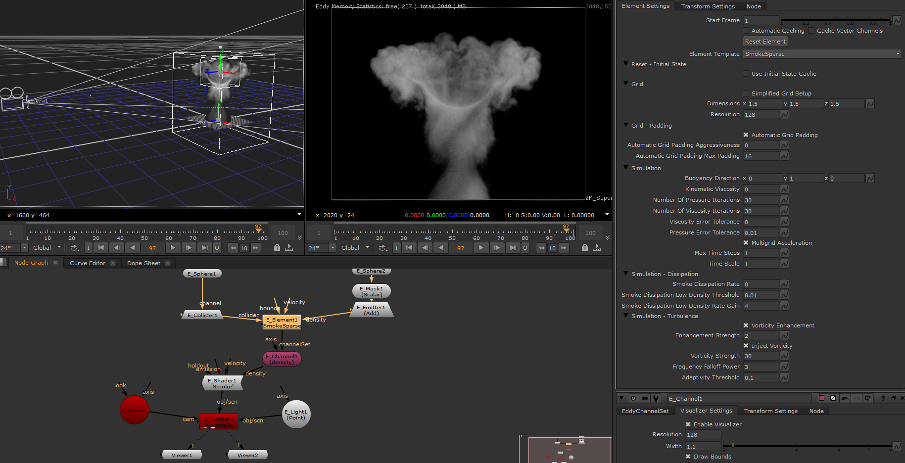
Smoke Element Node
This Element models buoyant smoke. The behavior of the smoke simulation is controlled through a number of parameters grouped in parameter sets. Parameters associated with a specific function are only shown if that function is enabled.
Inputs/Outputs
Connections |
ClassType |
Number |
Description |
|---|---|---|---|
bounds |
EddyBounds |
0-1 |
Eddy bounds defining the limits of the simulation space |
collider |
EddyCollider |
0+ |
Collision object(s) for the simulation to interact with |
density |
EddyEmitter (Scalar) |
1+ |
Density emission source used to inject smoke into the simulation |
velocity |
EddyEmitter (Vector) |
0+ |
Velocity emission source used for guiding the simulation |
Outputs |
EddyChannelSet |
1 |
Channel set containing the channels “density” and “velocity”. |
Grid parameter set
This parameter set controls the properties and behavior of the computational grid used to store the simulation data.
Note
When grid expansion is enabled the simulation space will periodically resize to track with the motion of the smoke. In order to avoid visual artifacts it is important that the the simulation has enough empty space (i.e. padding) around it that the smoke can move into. If the padding is insufficient the smoke may reach the edge of the current simulation space before a resize is triggered resulting in visual artifacts. Such problems can be resolved by increasing the amount of padding and/or increasing the resize frequency.
Note
Resizing the simulation space is a relatively expensive operation. For good performance when using grid expansion it is recommended to not resize too often and instead use sufficient padding with each resize.
Note
Generally avoid setting the Expansion Density Threshold too low as this will effectively preserve even the tiniest, effectively invisible, amount of density. An excessively low Expansion Density Threshold will prevent the grid expansion algorithm from reclaiming space where the smoke has thinned out below the visibility threshold.
Note
The edges of the simulation space approximate an open boundary allowing smoke to escape.
Parameter |
Values |
Description |
|---|---|---|
Dimensions |
(0,0,0)…(inf,inf,inf) |
The dimensions (extents) of the computational grid in scene units |
Resolution |
1…inf |
The number of voxels along the major axis of the domain. Higher values result in slower but higher fidelity simulations |
Grid Expansion |
True/False |
Enable dynamic expansion of the computational grid. This allows the simulation world to grow dynamically with the simulation ensuring there is enough space to track the smoke as it moves |
Expansion Min Resolution |
(1,1,1)…(inf,inf,inf) |
The lowest resolution allowed when using dynamic grid expansion |
Expansion Max Resolution |
(1,1,1)…(inf,inf,inf) |
The highest resolution allowed when using dynamic grid expansion - should be larger than Expansion Min Resolution |
Expansion Delay |
1…inf |
The number of computation cycles between each grid expansion event. Reshaping the grid is an expensive operation and performance can be gained by not doing this too often |
Expansion Padding |
1…inf |
The number of empty voxels added as padding around the smoke when the grid is reshaped. This is the space in which the smoke is free to move without artifacts before the grid needs to be reshaped again |
Expansion Density Threshold |
0…inf |
The smoke lower density threshold used by the expansion algorithm to determine what regions of the simulation to preserve and what regions can be safely culled |
Simulation parameter set
This parameter set controls aspects of the fundamental physics of the smoke and the strategies used to solve the underlying equations.
Note
Computing the pressure channel of a fluid is generally an expensive operation. As such it is tempting to keep the number of pressure iterations low to gain performance. This will however also reduce the accuracy of the simulation and the resulting fluid dynamics which will negatively affect the quality of the simulation. We recommend keeping this value above 10 if the multigrid option is enabled and above 70 if it is disabled. The exact value needed for high quality results depends on the grid size of the simulation and the complexity of any collision objects interacting with the simulation. Start with the recommended values and if the simulation is high resolution or complex consider increasing this number to see if it significantly improves the quality of your simulation. However, also note that if speed is paramount in many cases even a single iteration can be enough for decent quality if multigrid is enabled.
Note
Increasing the maximum number of substeps can significantly improve the quality of interactions with fast moving collision objects but will typically slow down the simulation.
Parameter |
Values |
Description |
|---|---|---|
Quality Mode |
True/False |
Allow methods that enhance simulation quality at a potentially significant performance cost |
Buoyancy Direction |
(-inf,-inf,-inf)…(inf,inf,inf) |
The direction of the buoyancy force. The magnitude of this vector determines the amount of buoyancy |
Kinematic Viscosity |
0…inf |
The kinematic viscosity of the fluid. Unit is m2/s |
Number Of Pressure Iterations |
1…inf |
The maximum number of computation cycles allowed to compute the pressure channel of the fluid |
Number Of Viscosity Iterations |
1…inf |
The maximum number of computation cycles allowed to solve for viscosity |
Pressure Error Tolerance |
0…inf |
The target pressure channel error tolerance in terms of amount of fluid compressibility |
Viscosity Error Tolerance |
0…inf |
The target viscosity channel error tolerance |
Multigrid Acceleration |
True/False |
Enable a method that greatly increases the quality of the pressure channel achieved for each cycle of the pressure solver. Keep enabled unless you experience artifacts or stability issues. |
Max Time Steps |
1…inf |
The maximum number of time steps the solver is allowed to take per frame |
Time Scale |
0…inf |
Time scaling constant. 2.0 means time flows 2x faster than normal. |
Note
The kinematic viscosity of various materials can be found in textbooks and to some extent online. See for example this table. Kinematic viscosity is often provided in the units mm2/s - in that case divide by 1 000 000 to get the correct value for use with Eddy.
Dissipation parameter set
This parameter set controls the rate at which smoke density dissipates over time.
Note
Residual smoke at low density tend to linger at the outskirts of the simulations. This is not always desired and can be cleared by using the Low Density Threshold and Low Density Rate Gain parameters to increase the rate of dissipation once the smoke density falls below the selected threshold.
Parameter |
Values |
Description |
|---|---|---|
Smoke Dissipation Rate |
0…inf |
The rate by which smoke dissipates |
Low Density Threshold |
0…inf |
Smoke density threshold below which dissipation increases in a non-linear fashion. |
Low Density Rate Gain |
1…inf |
Multiplier on the rate of non-linear dissipation below the threshold density |
Turbulence parameter set
This parameter set controls turbulence enhancement techniques. Vorticity is important for the look and feel of a smoke simulation and as such methods for controlling the amount and structure of vortices are an important artistic tool.
Note
Vorticity enhancement can greatly increase the visual complexity of the simulation. However, the enhancement strength must be set carefully as large values can add too much energy resulting in a noisy simulation. Start with a conservative value of 1.0 and increase as needed.
Note
The vorticity injection algorithm is adaptive and tries to select plausible regions where vorticity is injected. By increasing the Adaptivity Threshold you can make the algorithm more permissive in the regions it selects and by lowering the threshold towards 0.0 you can make it more restrictive. This control is very useful to prevent excessive turbulence being added to the wrong regions of the simulation and can greatly increase the visual quality of the result.
Note
Increasing the Adaptivity Threshold parameter will increase the size of the regions of the sim where vorticity injection is applied and thus the amount of energy added given the same Vorticity Strength. Thus increasing the Adaptivity Threshold will likely mean you will want to decrease Vorticity Strength and vice versa.
Parameter |
Values |
Description |
|---|---|---|
Vorticity Enhancement |
True/False |
Enable an algorithm that adds energy to vortices in the simulation. |
Enhancement Strength |
0…inf |
Determines the amount of energy added to the vortices. |
Vorticity Enhancement Adaptive |
True/False |
Enables adaptivity for the vorticity enhancement algorithm |
Frequency Falloff Power |
0…inf |
Controls the distribution of the size of the turbulence features generated. Larger values put more emphasis on higher frequencies whereas lower values put more emphasis on lower frequencies. |
Adaptivity Threshold |
0…1 |
Threshold determining how aggressively the vorticity adaptivity oracle selects valid regions for energy injection. Values above 1.0 can be used but tend to be very aggressive. |
Inject Vorticity |
True/False |
Enables an algorithm that synthesizes additional turbulence adding visual complexity to the simulation. |
Vorticity Strength |
0…inf |
Controls the magnitude of the synthesized turbulence. |
Frequency Falloff Power |
0…inf |
Controls the distribution of the size of the turbulence features generated. Larger values put more emphasis on higher frequencies whereas lower values put more emphasis on lower frequencies. |
Adaptivity Threshold |
0…1 |
Threshold determining how aggressively the turbulence adaptivity oracle selects valid regions for turbulence injection. Values above 1.0 can be used but tend to be very aggressive. |
Combustion Element Node
The combustion element models combustion dynamics, for example fire simulation. It adds a combustion model to the smoke element node and thus shares several parameters and inputs with this element.
Inputs/Outputs
Connections |
ClassType |
Number |
Description |
|---|---|---|---|
collider |
EddyCollider |
1+ |
Collision object(s) for the simulation to interact with |
density |
EddyEmitter (Scalar) |
1+ |
Density emission source used to inject smoke into the simulation |
velocity |
EddyEmitter (Vector) |
1+ |
Velocity emission source used for guiding the simulation |
fuel |
EddyEmitter (Scalar) |
1+ |
Fuel emission source used to inject unburnt fuel into the simulation |
temperature |
EddyEmitter (Scalar) |
1+ |
Temperature emission source used to provide initial heat to ignite the fuel |
Outputs |
EddyChannelSet |
1 |
Channel set containing the channels “density”, “velocity”, and “temperature” |
Smoke solver parameters
The basic parameters of the fire element are the same as found in the smoke element node. In addition the fire element has a set of parameters to control its combustion model:
Combustion parameter set
Parameter |
Values |
Description |
|---|---|---|
Cooling Rate |
0…inf |
The rate by which the soot cools through heat exchange with the surroundings |
Ignition Temperature |
0…inf |
The temperature at which the fuel ignites |
Combustion Temperature |
0…inf |
The temperature with which the fuel burns |
Fuel Carbon Amount |
0…inf |
The amount of carbon residue (i.e. soot) produced per unit of fuel consumed. 1.0 means each unit of fuel consumed generates 1 unit of smoke density |
Fuel Burn Rate |
0…inf |
The amount of fuel consumed per second as the fuel burns |
Fuel Expansion |
0…inf |
The amount of volume gain, i.e. expansion caused by the fuel igniting. 2.0 means that the simulated gas expands by 200% (i.e. a local 3x volume increase) per unit of fuel that has been consumed. |
Fuel Combustion Threshold |
0…inf |
The maximum fuel density allowed for ignition. |
Thermal Comductivity Multiplier |
0…inf |
Multiplies the amount of thermal conduction happens through air at constant pressure. Temperature exchange will occur with the neighbouring voxels and spread through the system. |
Thermal Solver Iterations |
0…inf |
The number of multigrid solver iterations used to compute the thermal conductivity. |
For a more in-depth description of the Eddy combustion model and its parameters see the simulation section on combustion.
Sparse Smoke and Fire Nodes
Far away from major simulation features channel data (velocity, density, temperature etc.) tend towards a constant ambient value - in most cases 0. This can be used to increase simulation efficiency by limiting the simulation to a region of space surrounding features of interest and at the edge of which the channel values are close to these ambient values. The sparse smoke and fire nodes allow efficient but more approximate simulation of smoke and fire by adaptively computing this region of interest - the Active Space.
Note
If the active space is too narrow the simulation will contain truncation artifacts as channel values will not be close to ambient values at the edge of the active space.
The sparse nodes have all the functionality of their dense counterparts but also a set of additional parameters related to controlling the active space.
Initial State
The initial state allows to specify a filepath to a .vdb file that will be loaded, when the element resets.
Note
Only the channels in the file, which match the channel names specified by the element will be loaded.
Initial State parameter set
The parameters that control the initial state:
Parameter |
Values |
Description |
|---|---|---|
Initial State Cache File |
String |
Specify a filepath to a .vdb file that will be loaded upon reset. |
Sparse space allocation
The active space is initially created by the emitters. It is then automatically reshaped as the simulation progresses to try and capture the relevant features of the simulation.
In order to maximize efficiency of sparse simulations it is important that the active space is as small as possible. The sparse node can ensure this automatically for all parts of the simulation expect for emission regions.
It is assumed that features of interest can exist anywhere within the bounding box of each emitter and thus to achieve high performance it is important that emitters have bounding boxes that are as tight as possible. If an emitter is not tightly bound the element will needlessly look for features of interest also in what is effectively empty space which will waste computation and thus slow down the simulation.
Note
Always strive to use as tight bounding boxes as possible for emission sources. This will avoid excessive allocation of simulation space around emitters and thus lead to more efficient simulations.
Note
Emitters will consider any channel registered as an expansion source as a space emission source. For these channels the emitter will allocate new space within the bounding box of the emitter source channel. Thus emitters that do not yet add to a channel may still emit empty space.
Note
Emitters provide an option to disable the insertion on a per emitter basis. This allows to speed up the solver. For instance vector field emitters often do not require additional allocation of space. By default all emitters emit new spaces by inserting the field bounds.
Note
The Eddy channel visualizer can visualize the current active space by ticking the ‘Draw Subbounds’ checkbox. This can be very useful for identifying performance and quality issues in sparse simulations.
Sparse grid parameter set
The sparse grid parameter set is similar to that of the smoke and fire elements above but contain a few additional controls:
Parameter |
Values |
Description |
|---|---|---|
Simplified Grid Setup |
True/False |
If enabled reduces the grid setup controls to a single parameter; voxel size. |
Voxel Size |
0…inf |
The size in scene units of each volumetric pixel (voxel). This is proportional to the smallest feature size that can exist in the simulation. |
Choosing a voxel size
The voxel size is approximately the size (in scene units) of the smallest feature that can be seen in the simulation. This will be the smallest feature in a collision geometry that can interact with the simulation as well as the size of the smallest flow features (e.g. eddies) that can exist in the simulation.
The optimal voxel size is the size that captures all flow features in a simulation. This is the Kolmogorov length scale which is typically quite small - in the order of millimeters. Thus for most scenes it is either impractically slow or impossible to use voxels this small. Instead a voxel size small enough to work in practice should be chosen.
A guideline for choosing an initial voxel size:
Identify a distance characteristic for your scene scale. A good rule of thumb is to use the longest side of the bounding box of your smallest emitter.
Choose how high resolution (the number of voxels) you want along that characteristic distance - i.e. how well you want for resolve the emitter. Think of this as the number of pixels along each axis in an image - few pixels leads to a coarse image that is fast to process, many pixels lead to a higher fidelity image but is slower to process.
Divide the characteristic distance by the chosen resolution number and the result is your voxel size.
For example: You want to simulate a campfire in a fireplace that is 0.75 meters in diameter. The fireplace is your emission region so your characteristic distance would be 0.75 meters. Your voxel size should be smaller than this distance, ideally much smaller. As a starting point you can for example choose a low resolution number of 10 which leads to a voxel size of 0.075 meters (0.75 divided by 10). This will be a coarse simulation but would do as a starting point - from here on you can make your voxel size smaller until you reach the desired level of fidelity or the limits of your hardware.
If you instead want to simulate a volcano the scene scale will be very different but the way to think is still the same: Your emitter would be the volcano crater. If we assume the crater is 100 meters in diameter that would be your characteristic distance. Choosing a (low) resolution factor of 10 that would lead to a voxel size of 10 meters (100 divided by 10). This would once again be a very coarse simulation but it is a starting point from which the voxel size can be reduced until you reach the desired level of fidelity or the limits of your hardware.
Note
Decreasing the voxel size increases the resolution and fidelity of the simulation at the cost of increased memory usage and longer simulatio times. The cost increase is approximately cubic - i.e. If you double your resolution (halving the voxel size) the memory and computation time increases by a factor 8. Depending on the number of timesteps per frame allowed the computation time could increase as much as by a factor 16. Yup - no free lunch - resolution is costly.
Grid padding parameter set
These parameters control how and when the active space is reshaped. Most importantly they control the distance between the simulation features of interest and the edges of the active space and thus the degree of truncation errors introduced in a sparse simulation. Performance is also heavily affected by these parameters.
Parameter |
Values |
Description |
|---|---|---|
Automatic Grid Padding |
True/False |
Enables a heuristic that attempts to automatically and continuously find the optimal active space for the simulation. |
Automatic Grid Padding Aggressiveness |
0…inf |
Controls how aggressively new space is added to the active set. Lower values result in a smaller active space which leads to faster but more approximate simulations. |
Automatic Grid Padding Max Padding |
1…inf |
This is a limit to the maximum distance in voxels that the active set is allowed to be expanded by the auto padding heuristic. This limit acts as a performance safe-guard to preventing excessive changes to the active set in the presence of shocks in the simulation. |
Grid Padding |
True/False |
Enables padding the active space based on smoke density |
Padding Amount |
1…inf |
The number of voxel layers with which the active space is padded |
Padding Density Cutoff Threshold |
0…inf |
The lower density threshold that define the region of interest which is the base for the active space. The region of interest is any part of space where the smoke density exceeds this threshold. |
Simple Sparse Smoke Node
This node is variant of the Sparse Smoke Element. The main differences is that it sacrifices quality for speed and memory consumption. The overall features and controls are a subset of the smoke element node and Sparse smoke and fire nodes , which makes this node a good entry point and lends itself well for background tasks.
E_Emitter
Emitters are responsible for creating and modifying channel data.
Usage
Emitters are typically used with an Eddy simulation element. An emitter can for example add smoke density or temperature to a specific location in space. It can also modify existing data during a simulation - for example by guiding the velocity channel of a simulation using external velocity data as a target.
Note
An emitter emits channel data of the same type as its input. If given a scalar channel input the emitter also outputs a scalar channel
Note
If an emitter multiplier is set to 0.0 the emission for this emitter will be skipped entirely.
Connections |
ClassType |
Number |
Description |
|---|---|---|---|
field |
EddyChannel |
1 |
Source channel for the emitter |
Output |
EddyEmitter |
1 |
Emitter for use with the E_Element |
Parameter |
Values |
Description |
|---|---|---|
Mode |
List |
Selected emission mode. See table below for descriptions. |
Insert Bounds |
True/False |
Inserts the bounding boxes of the connected field into the voxel layout, ensuring the space is allocated before the emission begins. |
Multiplier |
0…inf |
Multiplier applied to the input of the emitter node. In weak and strong guide mode this parameter is a multiplier on the guide strength. |
Direction Guide Strength |
0…inf |
Vector Blend mode parameter that controls the rate at which the guided channel velocity direction aligns with the guide channel. |
Acceleration Guide Strength |
0…inf |
Vector Blend mode parameter that controls the rate of acceleration when the guide channel magnitude exceeds that of the guided channel. |
Deceleration Guide Strength |
0…inf |
Vector Blend mode parameter that controls the rate of deceleration when the guide channel magnitude exceeds that of the guided channel. |
Note
The guide strength parameters are artistic controls and will need to be dialed in to get the desired level of guiding. Intuitively the value can be seen as controlling a force that attempts to align the guide and guided vector channels. Doubling the value doubles this force. To provide more fine-scale control there are three different parameters controlling acceleration, deceleration and direction respectively. It may for example be desirable to allow the guide to accelerate the guided channel but not decelerate it thus preventing the guide from removing energy. Another option is to allow the guide to only affect the direction of the channel but not its magnitude leaving more room for the simulation to determine the energy distribution.
Emission Mode |
Description |
|---|---|
Set |
Sets the value of the target channel to that of the input channel |
Additive |
Adds the input channel value to the target channel |
Subtract |
Subtracts the input channel value from the target channel |
Minimum |
Sets the target channel value equal to the minimum of the target and the input channels |
Maximum |
Sets the target channel value equal to the maximum of the target and the input channels |
Multiply |
Sets the target channel value equal to the product of the target and the input channels |
Divide |
Sets the target channel value equal to the target divided by the input |
Guide Weak |
Guides the target channel value towards that of the input in a weak (non-strict) manner. |
Guide Strong |
Guides the target channel value towards that of the input in a strong (strict) manner. |
Vector Blend |
Guides the target vector channel towards that of the input vector channel in a user controllable and non-trivial manner (see guide strength parameters above) |
Note
The difference between weak and strong guiding may be subtle in many cases but can still be useful as weak guiding leaves more room for the target channel to do its own thing.
Note
Weak and strong guiding can be used on both scalar and vector channels. Vector Blend guiding as the name implies only operate on vector data and is specifically intended for modifying velocity data in simulations.
A sparse smoke element smoke plume with an additive sphere emitter and a stationary sphere collider |
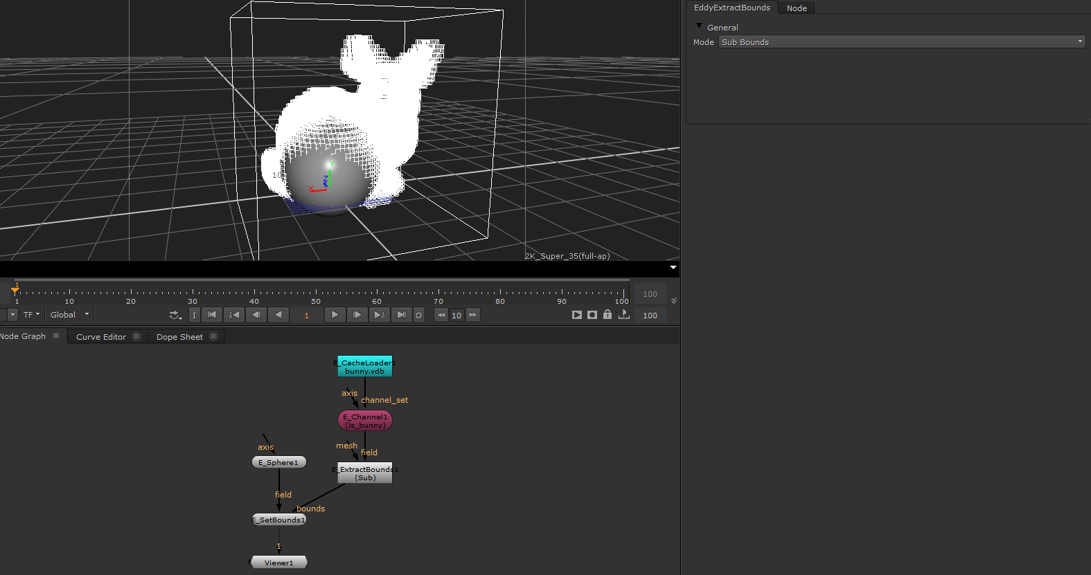
E_ExtractBounds
Extracts the bounds from a mesh or channel.
Usage
This node can be used to extract the bounds from either a mesh or an Eddy channel. These bounds can then be used by other nodes such as the E_SetBounds node or E_Element node.
Inputs/Outputs
Connections |
ClassType |
Number |
Description |
|---|---|---|---|
field |
EddyChannel |
0-1 |
An Eddy channel from which to extract the bounds |
mesh |
mesh |
0-1 |
A mesh geometry from which to extract the bounds |
Output |
EddyBounds |
1 |
An Eddy bounds object containing the extracted bounds |
Controls
Parameter |
Values |
Description |
|---|---|---|
Mode |
Root Bounds/Sub Bounds |
Controls whether only the overall root bounding box will be extracted, or if the more detailed sub-bounds should be extracted. |
Extracting the bounds from a channel loaded from a VDB cache, and applying them to a E_Sphere node |
E_FieldDebug
Allows numeric value visualization of Eddy Fields.
Usage
This node can be used to inspect the numeric values of any Eddy Field. It works both for scalar and vector fields and can be useful to debug complex field compositing operations.
Inputs/Outputs
Connections |
ClassType |
Number |
Description |
|---|---|---|---|
channel |
EddyChannel (Scalar/Vector) |
1 |
Scalar channel that will be used to drive the field debug node |
Controls
Parameter |
Values |
Description |
|---|---|---|
Enable Visualizer |
True/False |
Enables drawing |
Resolution |
1…512 |
Number of samples along the dominant axis of channel bounding box |
Width |
0…inf |
Multiplier for the channel bounding box or overall width when bounds aren’t provided |
Draw Bounds |
True/False |
Enable drawing of the bounding box wireframe |
Draw Subbounds |
True/False |
Enable drawing of the active space wireframe for sparse channels |
Numeric Text Color |
(0,0,0)…(inf,inf,inf) |
The color of the numeric text. |
Text Scale |
0…inf |
Scales the size of the text. |
Numeric Precision |
1…inf |
The floating point precision. Controls the maximum number of digits displayed after the decimal separator. |
Scientific Notation |
True/False |
Use scientific notation to display floating point numbers. |
Draw Background |
True/False |
Adds a background behind each text to make the text more readable. |
Background Color |
(0,0,0)…(inf,inf,inf) |
The color of the background area behind the text. |
Display Values In Range |
True/False |
Only values that are within the range specified will be displayed. For vector values the magnitude is used to check the range. |
Minimum Value Range |
-inf…inf |
Minimum range of the values that will be displayed. |
Maximum Value Range |
-inf…inf |
Maximum range of the values that will be displayed. |
Crop Window |
True/False |
Enable GL corner points to adjust the visualizer draw region |
Reset Crop |
Button |
Reverts the crop window to the original bounding box from the channel |
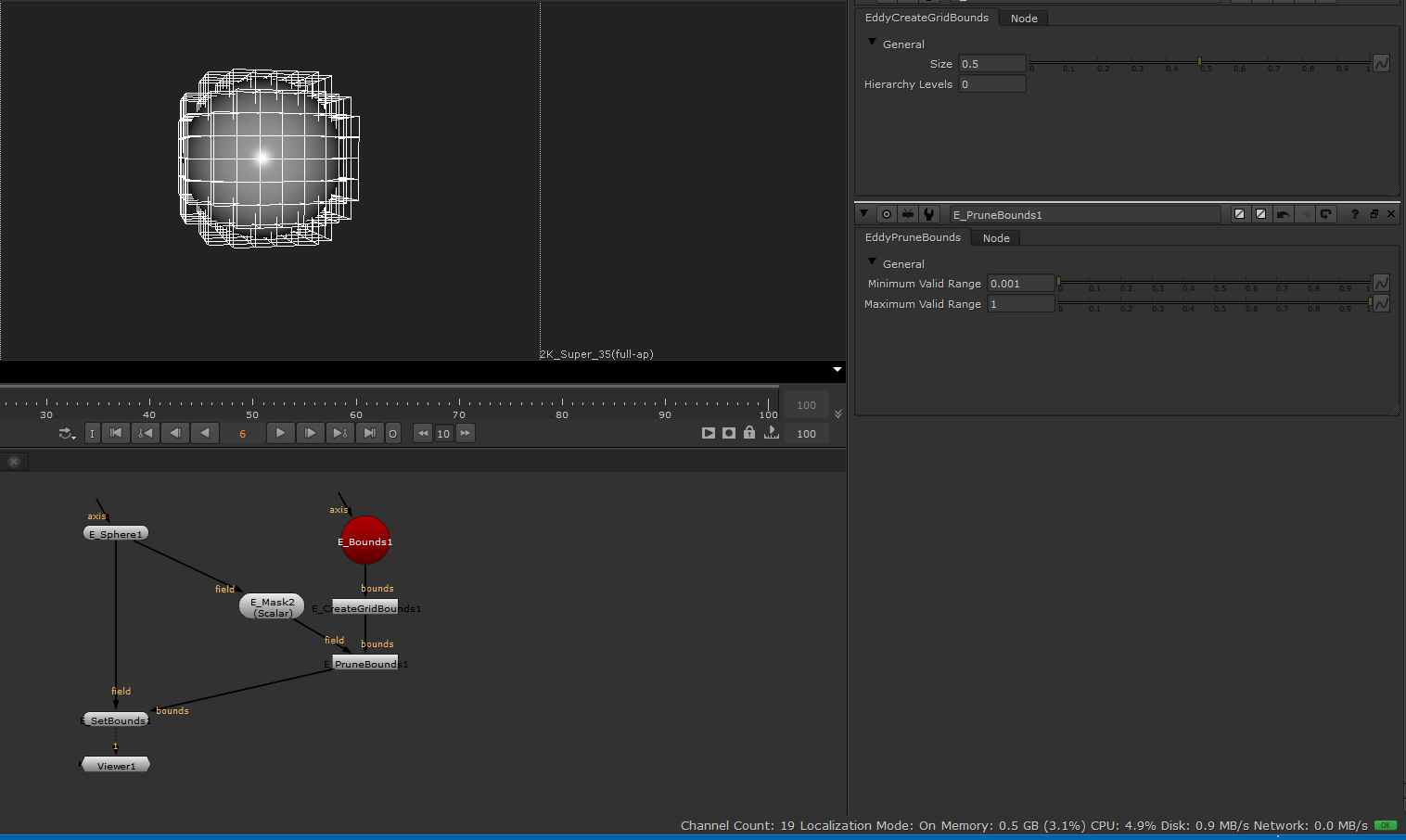
E_PruneBounds
Samples the supplied volume in the area of each provided bounding box 4x4x4 times and deletes it if none of the samples fall within the valid range.
Usage
The PruneBounds node can be used to remove bounding boxes from a collection. This can be useful when one needs to optimize emission areas or fields for rendering.
Inputs/Outputs
Connections |
ClassType |
Number |
Description |
|---|---|---|---|
bounds |
Bounds |
0-1 |
A bounding box data set the pruning operation will use as source. |
field |
Field |
0-1 |
A scalar field that will be sampled indside each bounding box. |
Output |
Bounds |
1 |
The pruned bounding box data set. |
Controls
Parameter |
Values |
Description |
|---|---|---|
Minimum Valid Range |
-inf/+inf |
The minimum validity range threshold all voxels of a bounding box need to pass. |
Maximum Valid Range |
-inf/+inf |
The maximum validity range threshold all voxels of a bounding box need to pass. |
The bounding boxes after the pruning operation. |